A gas sensor has become an indispensable tool in various industries due to increasing awareness of environmental protection and safety concerns. For safety and pollution control, gas sensors are used to detect and measure the concentration of various gases in the air. In this article, we will learn more about gas sensors, their construction, types, and how they can be used to measure the required types and concentrations of gases in our atmosphere.
What Is a Gas Sensor?
A gas sensor is a device designed to detect the presence and measure the concentration of specific gases in the surrounding environment. It operates on the principle of converting the chemical or physical interaction between the target gas and a sensing element into an electrical or optical signal, which can then be quantified and analyzed. Gas sensors are essential tools used in various industries and applications for safety, environmental monitoring, industrial process control, and healthcare.
Gas sensor classification is intricate, involving numerous considerations such as operating principles, characteristics, measurement techniques, materials, manufacturing processes, detection targets, and application domains. Currently, classification based on distinct working principles is predominantly utilized. This article will comprehensively present five types of gas sensors.
1.Semiconductor Gas Sensor
Semiconductor gas sensors constitute approximately 60% of all gas sensors deployed. They serve to detect the presence of gases in the surrounding environment by gauging alterations in the electrical resistance of a semiconductor material upon interaction with the target gas.
Typically, the semiconductor material utilized in these sensors comprises metal oxides such as tin oxide, tungsten oxide, or zinc oxide. Upon entry of the gas into the sensor, the gas molecules engage with the semiconductor material, inducing a shift in its electrical conductivity. This alteration in conductivity directly correlates with the concentration of the gas.
2.Electrochemical Gas Sensors
- Electrochemical gas sensors quantify the current produced during the oxidation or reduction of the target gas at the electrode, utilizing this current to ascertain the gas concentration. These sensors encompass four distinct types: primary battery type, constant potential electrolysis cell type, concentration cell type, and limiting current type.
- Primary battery type gas sensors, also referred to as Galvanic cell type gas sensors, fuel cell type gas sensors, or self-generating battery type gas sensors, operate akin to dry batteries. However, in this case, gas electrodes replace the carbon-manganese electrodes. For instance, in an oxygen sensor, oxygen undergoes reduction at the cathode, with electrons flowing through the ammeter to the anode where lead metal undergoes oxidation. The resultant current is directly proportional to the oxygen concentration. These sensors are proficient in detecting oxygen, sulfur dioxide, and other gases.
- Constant potential electrolysis cell type gas sensors excel in detecting reducible gases. Unlike primary battery type sensors, the electrochemical reaction in this type of sensor occurs under forced current, utilizing Coulomb analysis to determine the quantity of substance being measured, as per Faraday's law. Such sensors are employed in detecting gases like carbon monoxide, hydrogen sulfide, hydrogen, ammonia, and hydrazine, and serve as the primary sensors for toxic and hazardous gas detection.
- Concentration cell type gas sensors rely on gases with electrochemical activity to spontaneously generate a concentration electromotive force between the two sides of an electrochemical cell. The magnitude of this electromotive force correlates with the gas concentration. An example of this sensor type is the oxygen sensor utilized in automobiles and solid electrolyte carbon dioxide sensors.
- Limiting current type gas sensors operate on the principle that the limiting current in an electrochemical cell is linked to the concentration of charge carriers. There exists an oxygen (gas) concentration sensor leveraging this principle, employed for oxygen detection in automobiles and measuring the oxygen concentration in steel melt.
3.Infrared Gas Sensor
An infrared gas sensor functions as a device detecting the existence of diverse gases in the atmosphere through the absorption of infrared radiation by the gas molecules.
4. Photoacoustic Gas Sensor
Traditionally, a photoacoustic gas sensor refers to the integration of non-dispersive infrared (NDIR) and photoacoustic technologies to gauge gas concentration.
5.MEMS Sensor
MEMS, which stands for Micro-Electro-Mechanical Systems, represents a technology merging electronic circuits with micro-mechanical structures. Frequently employed in crafting compact sensors and actuators, MEMS sensors are diminutive devices amalgamating electronic and mechanical elements on a microscopic level to detect and quantify various physical phenomena like acceleration, pressure, temperature, motion, and more.
Gas Sensor Construction
Among the types listed above, the Metal oxide semiconductor-based gas sensor stands out as the most frequently utilized. Regardless of the specific type, all gas sensors will incorporate a sensing element comprising the following components.
- Gas sensing layer
- Heater Coil
- Electrode line
- Tubular ceramic
- Electrode
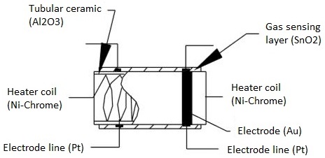
The following image depicts the components found in a metal oxide gas sensor.
The function of each of these components is outlined as follows:
Gas sensing layer: This component serves as the core of the sensor, detecting fluctuations in gas concentration and inducing changes in electrical resistance. Essentially a chemiresistor, it alters its resistance based on the concentration of specific gases in the environment. Typically composed of Tin Dioxide (SnO2), which inherently possesses excess electrons (donor element), the sensing element undergoes resistance changes when toxic gases are detected. This variation in resistance influences the flow of current through the element, reflecting alterations in gas concentration.
Heater coil: The heater coil's role is to preheat the sensing element, enhancing its sensitivity and efficiency. Constructed from Nickel-Chromium, which boasts a high melting point, the coil maintains a constant temperature without melting.
Electrode line: Given that the sensing element generates minute currents upon gas detection, it's crucial to facilitate the efficient flow of these currents. Platinum wires, serving as electrode lines, aid in the seamless movement of electrons.
Electrode: Acting as the interface where the output of the sensing layer connects to the electrode line, the electrode allows the output current to flow to the desired terminal. Typically crafted from Gold (Au), renowned for its excellent conductivity.
Tubular ceramic: Positioned between the heater coil and gas sensing layer, the tubular ceramic, usually comprised of Aluminum oxide (Al2O3), boasts a high melting point. This feature aids in maintaining the preheating of the sensing layer, thereby ensuring high sensitivity and efficient output current.
Mesh over the sensing element: To safeguard both the sensing elements and the setup from damage, a metal mesh is deployed. Additionally, it acts as a barrier against dust particles, preventing them from infiltrating the mesh and safeguarding the gas sensing layer against corrosive particles.
How Does a Gas Sensor Work?
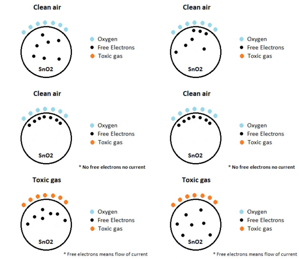
The efficacy of a gas sensor in detecting gases hinges on the ability of the chemiresistor to conduct current. Tin Dioxide (SnO2) is the most prevalent chemiresistor utilized, characterized as an n-type semiconductor with free electrons, also known as donors. Typically, the atmosphere contains a higher concentration of oxygen than combustible gases. Oxygen particles attract the free electrons within SnO2, causing them to migrate to the surface of the material. Consequently, in the absence of available free electrons, the output current remains at zero. The animated gif below illustrates oxygen molecules (blue) drawing in the free electrons (black) within SnO2, hindering their ability to conduct current.

In environments containing toxic or combustible gases, these reducing gases (orange) interact with adsorbed oxygen particles, disrupting the chemical bond between oxygen and free electrons, thereby releasing the free electrons. As these electrons return to their original state, they regain their capacity to conduct current. This conductivity is directly proportional to the quantity of free electrons present in SnO2; thus, highly toxic gases yield a greater abundance of free electrons, resulting in heightened conductivity.
How to use a Gas sensor?
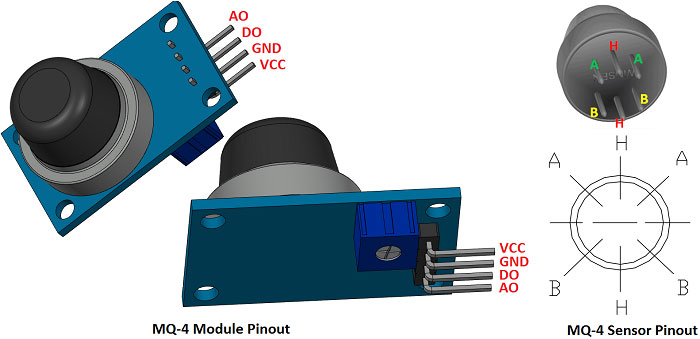
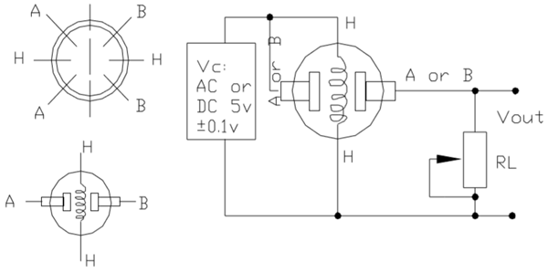
A standard gas sensor comprises six terminals, with four terminals labeled as A, A, B, and B serving as input or output, while the remaining two terminals denoted as H, H are dedicated to heating the coil. Among these four terminals, two terminals from each side are reversible, functioning interchangeably as input or output, as illustrated in the circuit diagram.

These sensors are normally available as modules (shown right), these modules consist of the gas sensor and a comparator IC. Now let’s see the pin description of the gas sensor module which we will generally use with an Arduino. The gas sensor module basically consists of 4 terminals
- Vcc – Power supply
- GND – Power supply
- Digital output – This pin gives an output either in logical high or logical low (0 or 1) that means it displays the presence of any toxic or combustible gases near the sensor.
- Analog output – This pin gives an output continuous in voltage which varies based on the concentration of gas that is applied to the gas sensor.
As previously mentioned, the output of a gas sensor typically remains minuscule (measured in millivolts), necessitating the integration of an external circuit to obtain a digital high-low output from the sensor. To achieve this objective, a comparator (LM393), adjustable potentiometer, along with various resistors and capacitors, are employed.
The LM393 comparator serves the purpose of receiving the output from the sensor, comparing it with a reference voltage, and determining whether the output is logically high or not. On the other hand, the adjustable potentiometer is utilized to establish the desired threshold value for the gas concentration, above which the digital output pin should transition to a high state.
The following diagram illustrates the fundamental circuitry of a gas sensor within a gas sensor module.

In the depicted diagram, A and B denote the input and output terminals, respectively. It's noteworthy that these terminals are reversible, implying that either of the paired terminals can function as input or output. H signifies the terminal designated for the heater coil. The variable resistor serves the purpose of adjusting the output voltage while maintaining high sensitivity.
When no voltage is applied to the heater coil, the output current remains minimal, nearly negligible or approximately zero. However, upon applying sufficient voltage to the input terminal and heater coil, the sensing layer becomes active, primed to detect any nearby combustible gases. Initially assuming the absence of toxic gases in proximity to the sensor, the resistance of the layer remains unaltered, resulting in negligible output current and voltage.
Now, envision a scenario where toxic gas is present nearby. With the heater coil preheated, detecting combustible gases becomes more facile. As the sensing layer interacts with the gases, the resistance of the material fluctuates, consequently causing variations in the current flowing through the circuit. These fluctuations can be observed at the load resistance (RL).
The load resistance (RL) value can range from 10KΩ to 47KΩ. The precise value of RL can be determined by calibrating it against known gas concentrations. Opting for a lower load resistance reduces circuit sensitivity, while a higher load resistance enhances sensitivity.


Comments