RF switches serve the purpose of directing radio frequency (RF) signals among different inputs and outputs. They find extensive application in RF and microwave test systems, facilitating the routing of signals between instruments and devices under test (DUT). Utilizing RF switches enables the execution of multiple tests without necessitating alterations to the setup, thereby enhancing efficiency by minimizing the frequency of connections and disconnections.
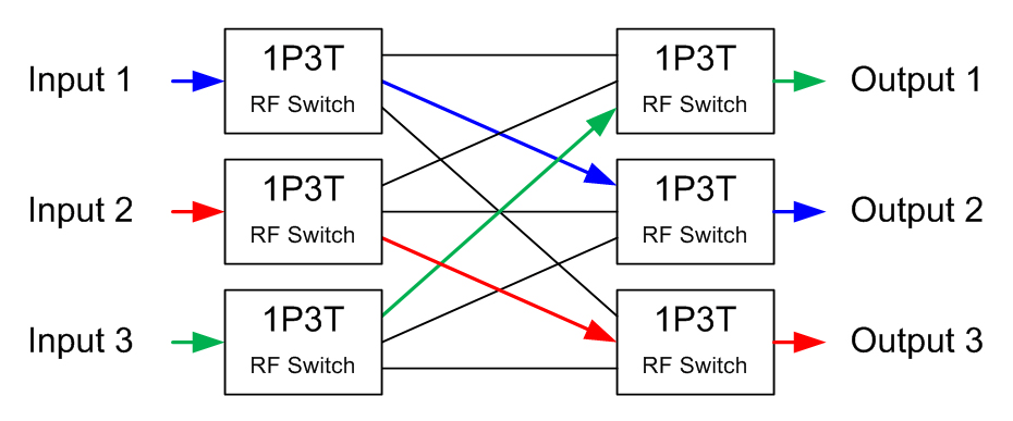
To exemplify the simplification of intricate signal routing through the use of RF switches, let's consider matrix switching. In the illustration below, six single-pole, triple-throw (1P3T) switches are employed to route three RF signals. The colored lines indicate the trajectory of each input signal, with the flexibility to reroute signals via any of the black lines by adjusting the switches. This design exclusively relies on switches, eliminating the need for power dividers or attenuators, thereby ensuring low insertion loss and exceptionally high signal isolation.
Based on the switching action of RF switches, there are two different types of switches which can be classified as follows:
Electromechanical Switches
Electromechanical switches incorporate metal contacts that can either be in a physically open state, halting the flow of current or signal, or closed, completing the circuit and enabling current to pass through. These switches are characterized by the number of circuits they can connect, known as "poles," and the distinct positions they can assume, referred to as "throws." For instance, a single pole, single throw (SPST) switch functions as a basic on-off device, either establishing or breaking one circuit. Conversely, a double pole, single throw (DPST) switch operates two connected circuits simultaneously. In contrast, a double throw (DT) switch can alternate between two separate circuit paths. Various schematics of electromechanical switches are depicted below.
Electromechanical switches offer versatility across broad frequency ranges and boast features such as low signal loss and minimal cross talk between channels. However, they present certain drawbacks due to their reliance on physical movement for operation:
- Unreliable or slow switching caused by contact bounce.
- Arcing between contacts.
- Susceptibility to electromagnetic interference.
Solid State Switches
Solid-state switches are semiconductor devices that operate without mechanical switching mechanisms, enabling them to switch signals rapidly. Due to their robust resistance to shock, vibration, and mechanical wear, they are perceived as more reliable and durable compared to electromechanical switches. However, solid-state switches typically exhibit higher insertion loss than their electromechanical counterparts.
Solid-state switches leverage three primary semiconductor technologies to facilitate effective signal switching:
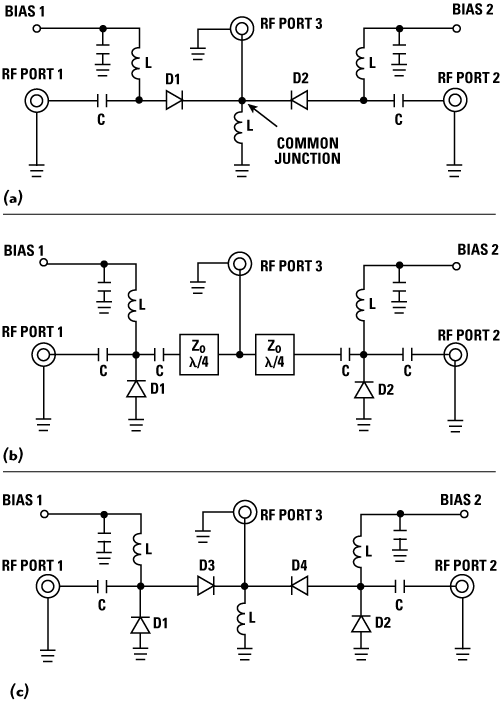
PIN Diode Switches: PIN diodes function as variable resistors at RF and microwave frequencies. Controlled by current, they adjust their resistance to either a lower state (ON or "make") or a higher state (OFF or "break"). Despite their capability to handle large RF signals with minimal control current, PIN diode switches are generally limited to lower frequency operations (< 1 MHz). Within this range, they offer superior isolation characteristics, especially at higher frequencies. The image below depicts three different SPDT PIN diode switch configurations: series PIN (top), shunt PIN (middle), and series-shunt PIN (bottom).
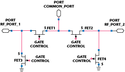
Field Effect Transistor (FET) Switches: FET switches utilize semiconductor devices to regulate the conductivity of a channel within the semiconductor material. They consume less current and exhibit higher insertion loss than PIN diode switches. FET switches feature excellent isolation at lower frequency ranges but tend to switch more slowly compared to PIN diode switches. Isolation characteristics may degrade at higher frequencies due to drain-to-source capacitance.
Hybrid Switches: Hybrid switches integrate both PIN diodes and FETs, combining the advantages of both switch types. They consume moderate power, offer excellent isolation at high frequencies, and demonstrate average switching speeds.
Manual Switches
Apart from solid-state and electromechanical variants, certain RF switches are manually operated. These devices necessitate human intervention to manipulate a knob or slide, facilitating switching. Manual switches commonly accommodate high-power signals and find frequent application in toggling between multiple antennas and RF transmitters/receivers.
Factors to Consider When Selecting RF Switches
When selecting RF switches for specific applications, several factors must be carefully considered to ensure optimal performance and compatibility. Here are the key factors to take into account:
- Frequency Range: Determine the operating frequency range required for your application. Ensure that the RF switch's frequency capabilities align with the frequency range of the signals being handled.
- Insertion Loss: Evaluate the insertion loss of the RF switch, which refers to the amount of signal power lost when passing through the switch. Lower insertion loss is desirable for maintaining signal integrity.
- Isolation: Consider the isolation performance of the RF switch, which refers to its ability to prevent unwanted signals from leaking between different ports. Higher isolation ensures minimal crosstalk and interference.
- Switching Speed: Assess the switching speed of the RF switch, which determines how quickly it can transition between different signal paths. Faster switching speeds are advantageous for applications requiring rapid signal routing.
- Power Handling: Determine the power handling capability of the RF switch, which specifies the maximum power levels it can safely handle without degradation or damage.
- Control Interface: Consider the control interface of the RF switch, such as whether it requires DC voltage, TTL signals, or other control mechanisms for operation. Ensure compatibility with your system's control scheme.
- Reliability and Durability: Evaluate the reliability and durability of the RF switch, particularly in terms of mechanical robustness, temperature stability, and longevity. Choose switches that can withstand the environmental conditions and operational requirements of your application.
- Size and Form Factor: Consider the physical size and form factor of the RF switch, especially if space is limited or if integration into a compact system is necessary.
- Cost: Assess the cost-effectiveness of the RF switch, taking into account factors such as initial purchase price, long-term maintenance costs, and overall value for your application.
- Application Specific Requirements: Take into consideration any specific requirements or constraints of your application, such as environmental conditions, regulatory compliance, and compatibility with existing equipment or systems.
By carefully evaluating these factors and selecting RF switches that best meet your application's needs, you can ensure reliable performance and optimal functionality in your RF system.
Comments