wang meihong's Posts (64)

Sort by
LED downlights have become a popular choice for homeowners and businesses alike due to their energy efficiency and long lifespan. However, one common issue that can arise with LED downlights is flickering. Flickering lights not only disrupt the ambiance but can also indicate underlying issues that need to be addressed. In this article, we'll explore the causes of LED downlight flickering and provide effective solutions to resolve them.


9 Common Causes Behind LED Light Flickering

 
1.Downlight & Dimmer Compatibility
 
LED downlights are often designed to work with specific dimmer switches. Incompatibility between the downlight and the dimmer switch can lead to flickering issues. Traditional dimmer switches are designed for incandescent bulbs, which have different power requirements compared to LED lights. When an incompatible dimmer switch is used with LED downlights, it can result in inadequate power delivery, causing flickering. This occurs because the dimmer may not provide a stable current flow suitable for the low wattage and unique electrical characteristics of LED lights.
 
Solution:
 
To resolve this, ensure that the dimmer switch is compatible with LED lights. Look for dimmer switches labeled as "LED compatible" or "LED dimmer switches" and consider consulting with a qualified electrician for assistance.
 
2.The Ripple Effect
 
The ripple effect is a consequence of "ripple control," a method of electricity load management. Ripple control is widely practiced in Australia, particularly in NSW and QLD, allowing electricity suppliers to regulate peak demand for electricity.

Without ripple control, electricity grids would struggle to meet demand, risking damage to power plant facilities and prolonged outages. To mitigate this, ripple control entails reducing energy supplied to specific areas of AU during peak demand periods, typically between 7-10 in the morning and 5-10 in the evening.

While ripple control helps manage energy demand, it can lead to LED lights flickering due to their low energy requirements. This effect becomes more pronounced in households with multiple appliances, which continue to draw energy even as the supply diminishes. Consequently, insufficient energy remains to power LED lights effectively.
 
Solution:
 
To address the ripple effect, stabilize the electrical supply by using voltage stabilizers or surge protectors, secure all electrical connections to prevent intermittent flickering, and invest in high-quality LED downlights designed to withstand electrical disturbances.
 
3.Dusty or Dirty Sockets
 
Over time, dust may gather on the surfaces of your LED bulbs and seep into the sockets. If you haven't cleaned your lighting fixtures in a while, accumulated dirt could be the culprit behind your flickering bulbs.
 
Solution:
 
Clean the sockets regularly using a soft brush or compressed air to remove any debris. Ensure that the sockets are dry before reinserting the LED downlight to prevent moisture-related issues.
 
Read more…

How to Prevent Poor Solder Wetting

In many cases, inadequate solder wetting is responsible for subpar joints and unreliable soldering processes. Nonetheless, the prevalence of this issue doesn't imply inevitability. By employing effective strategies, you can proactively prevent inadequate solder wetting, ensuring durable and reliable joints.
 

What Is The Soldering Wetting Process?

 
Let's begin by precisely defining the wetting process.

During soldering, two metals are joined using a solder alloy, forming a permanent fusion between them. However, behind the scenes, a crucial wetting process must occur.

Wetting involves the solder metal bonding with the metal surfaces of your PCB or components. As the solder melts, it transforms into a fluid state and adheres to the component, establishing the essential solder joint for your process.

For the wetting process to occur successfully, specific environmental conditions must be met, including:
 
  • A clean copper surface devoid of any contaminants.
  • Attainment of the optimal temperature.
 
It's worth noting that some metals exhibit greater receptivity to the wetting process, while others pose more of a challenge.
 

What Is Solder Wetting?

 
Solder wetting refers to the ability of molten solder to spread and adhere to the surfaces of the materials being joined during the soldering process. It is essential for creating strong, reliable solder joints. Efficient wetting ensures that the solder forms a smooth, uniform bond with the substrate, promoting good electrical and thermal conductivity. Inadequate wetting results in solder that does not spread evenly or adhere properly, leading to weak joints, poor electrical connections, and increased risk of failure.

Effective solder wetting, and consequently, metal bonding, necessitates a specific environment for proper execution. This process relies on a clean copper surface devoid of contaminants and heated to the appropriate temperature. Below, we will delve into the significance of achieving optimal solder wetting and outline strategies to prepare your operation for successful outcomes.
 

Why Is Good Wetting Soldering Important?

 
Effective solder wetting is essential for achieving proper metal joining. Without it, metals may fail to adhere adequately and are unlikely to meet industry standards for acceptable use, rendering them essentially defective. Optimal solder wetting results in well-made solder joints capable of withstanding the test of time.

Distinguishing good solder wetting is often possible by its appearance. It produces a shiny, smooth-looking solder that has reached maximum flow. Conversely, poor solder wetting is frequently identifiable. The solder may appear grainy, dull, and porous, indicating inadequate adhesion to components. Such solder is often unusable in commercial settings, leading to wasted time, capital, and productivity.
 
Read more…

Endoscopy Vs Laparoscopy

You've likely encountered mentions of laparoscopy surgery and endoscopy on multiple occasions. Did you know that these are distinct procedures falling under the minimally invasive category, chosen by over 13 million individuals worldwide each year?

In recent years, advancements in medicine have been significant. Modern science continually strives to enhance accessibility and affordability of treatments while reducing patient discomfort and treatment duration. Despite the natural inclination to avoid pain, seeking timely medical attention is often crucial in preventing further complications.

Thanks to advancements in technology and medical practices, procedures and surgeries once associated with significant discomfort are now conducted with minimal invasion and shorter recovery periods. Laparoscopy and Endoscopy are prime examples, as they involve minimal skin incisions, leading to reduced pain and faster recovery times.

However, what sets Laparoscopy and Endoscopy Surgery apart? Aren't they essentially the same thing? Despite common confusion, these surgeries have distinct differences.
 

What Is Laparoscopy Surgery?

 
Laparoscopy surgery, also known as minimally invasive surgery or keyhole surgery, is a surgical technique that involves making small incisions in the abdomen through which specialized instruments and a tiny camera called a laparoscope are inserted. The laparoscope transmits images of the inside of the abdomen to a monitor, allowing the surgeon to visualize the internal organs and perform the procedure.

During laparoscopy surgery, carbon dioxide gas is often used to inflate the abdomen, creating space for the surgeon to work and improving visibility. The surgeon then performs the necessary surgical procedure, such as removing diseased tissue, repairing organs, or performing biopsies, using small instruments inserted through the incisions.
 

What Is Endoscopy?

 
Endoscopy is a medical procedure that involves the use of a flexible, slender tube with a light and camera at its tip, called an endoscope, to examine the interior of the body. The endoscope is inserted into the body through a natural opening or a small incision and allows the physician to visualize and inspect various organs and structures inside the body on a monitor.

Endoscopy is commonly used to diagnose, monitor, and treat a wide range of medical conditions affecting different parts of the body. Some common types of endoscopy procedures include:
 
  1. Upper gastrointestinal endoscopy (esophagogastroduodenoscopy or EGD): This procedure involves inserting the endoscope through the mouth to examine the esophagus, stomach, and duodenum (the first part of the small intestine). It is often used to investigate symptoms such as difficulty swallowing, abdominal pain, or gastrointestinal bleeding.
  2. Colonoscopy: In this procedure, the endoscope is inserted through the rectum to examine the large intestine (colon) and the rectum. Colonoscopy is a screening test for colorectal cancer and is also used to diagnose and treat conditions such as inflammatory bowel disease and colorectal polyps.
  3. Bronchoscopy: Bronchoscopy involves inserting the endoscope through the mouth or nose and into the airways (bronchi and lungs). It is used to diagnose and treat conditions affecting the respiratory system, such as lung infections, tumors, or blockages.
  4. Cystoscopy: This procedure involves inserting the endoscope through the urethra into the bladder to examine the lining of the bladder and urethra. Cystoscopy is used to diagnose and treat conditions affecting the urinary tract, such as urinary tract infections, bladder stones, or bladder cancer.
  5. Arthroscopy: Arthroscopy is a type of endoscopy used to visualize and treat joint problems, such as damaged cartilage or ligaments, within the knee, shoulder, hip, or other joints.
 
Endoscopy offers several benefits, including the ability to directly visualize internal structures without the need for invasive surgery, the ability to obtain tissue samples (biopsies) for further examination, and the potential for certain therapeutic interventions during the procedure. It is generally a safe and well-tolerated procedure, although complications such as bleeding, infection, or perforation of organs may occur rarely.
 
Read more…

What Is a Programmable LED Driver?

The market is witnessing an increasing array of LED drivers with programmable features for output current. LED drivers serve as power supplies essential for regulating the power requirements of LEDs. With their programmable capabilities, these drivers enhance the output of current lighting while providing a higher level of hardware flexibility. In this blog post, you'll gain insight into the fundamentals of programmable LED drivers and discover the key parameters to consider.
 

What is Programmable LED Driver?

 
A Programmable LED driver offers users the ability to configure output current, dimming mode, timing dimming, CLO, and other functions via computer or cellphone. These drivers have emerged in response to the evolving hardware demands in the market. Lighting designers sought to develop products requiring less inventory while offering greater flexibility. For example, users can adjust the LED driver's output over time while maintaining a consistent power output.

LED drivers play a critical role in safeguarding bulbs from voltage fluctuations by regulating the power necessary for LEDs. They function as power supplies, ensuring operational stability. Indeed, every LED light relies on a driver to maintain it within its operational parameters.

Various types of drivers are available depending on the LED's energy consumption. Internal and external drivers represent optimal choices for safeguarding LED bulbs. What sets programmable LED drivers apart in popularity? They excel at synchronizing the output of household or office lighting with the driver through features such as adjustable output current and dimming curves, which describe how a dimmer adjusts voltage output relative to a control signal input.
 

Benefits of Programmable LED Driver

 
Programmable LED drivers offer several benefits that contribute to enhanced flexibility, efficiency, and performance in lighting systems:
 
  1. Customizable Output: One of the primary advantages of programmable LED drivers is the ability to customize output parameters such as current, dimming levels, and timing. This customization allows for tailored lighting solutions that meet specific requirements for different applications and environments.
  2. Flexibility: With programmable features, LED drivers can adapt to changing lighting needs and preferences. Whether it's adjusting brightness levels, implementing dynamic lighting effects, or integrating with smart control systems, programmable drivers offer greater flexibility in lighting design and operation.
  3. Energy Efficiency: Programmable LED drivers enable optimization of energy usage by adjusting output parameters based on real-time conditions and user preferences. This optimization helps to minimize energy consumption while maintaining desired lighting levels, resulting in energy and cost savings over time.
  4. Enhanced Control: By enabling remote programming and control via computers or mobile devices, programmable LED drivers provide users with convenient access to manage and monitor lighting systems. This remote control capability facilitates easier operation, troubleshooting, and maintenance, especially in large-scale installations or IoT-enabled setups.
  5. Adaptive Lighting: Programmable drivers support advanced lighting features such as color tuning, dynamic color temperature adjustments, and circadian lighting. These capabilities allow for adaptive lighting schemes that can mimic natural light patterns, enhance visual comfort, and promote well-being in indoor environments.
  6. Future-Proofing: As lighting technologies and requirements evolve, programmable LED drivers offer a future-proof solution that can accommodate emerging trends and standards. Their versatile nature allows for software updates and feature enhancements, ensuring compatibility and longevity in lighting installations.
 
Overall, the benefits of programmable LED drivers include increased customization, flexibility, energy efficiency, control, adaptability, and future-proofing, making them an ideal choice for modern lighting applications across various sectors.
 
Read more…

How to Fix Orange Flame on Gas Stove

The presence of an orange flame on your gas stove may seem innocuous, but it actually signals significant concerns. Many individuals perceive yellow or orange flames as typical, unaware of the potential dangers they pose. However, such flames pose risks to both your kitchen and your health, potentially leading to hazardous situations.
 
Consistently burning orange flames on your gas stove indicate incomplete combustion of gas, which can have adverse effects on your health and kitchen utensils. It's crucial to address this issue promptly by fixing or adjusting your burners.
 
In this article, we'll delve into what an orange flame signifies, its potential harm, and effective ways to rectify it.
 
gas stove flame is orange
 

What Does Orange Flame on Gas Stove Mean?

 
If your gas stove emits an orange flame, it indicates incomplete combustion, resulting in the production of carbon monoxide—a toxic gas associated with severe health risks.
 
Cooking over an orange flame can introduce issues with food quality, making it inadvisable. Moreover, exposing your family to the dangers of carbon monoxide poisoning is a risk that should not be taken lightly. Several factors can contribute to the appearance of an orange flame on your gas stove:
 
  1. Airflow Issues: Insufficient airflow into the burner can hinder proper combustion, resulting in an orange flame. This may occur due to clogged burner openings, dirt or debris in the burner, or inadequate ventilation around the stove.
  2. Gas Pressure: Fluctuations in gas pressure can affect the combustion process, leading to an orange flame. Low gas pressure can result in incomplete combustion and the production of a yellow or orange flame.
  3. Dirty or Worn Burners: Buildup of grease, food residue, or rust on the burner surface can impede the flow of gas and disrupt combustion, causing the flame to appear orange.
  4. Moisture or Contaminants in the Gas: Moisture or impurities in the gas supply can interfere with combustion, altering the color of the flame.
  5. Incomplete Mixing of Air and Gas: If the air and gas mixture entering the burner is not properly balanced, combustion may be incomplete, leading to an orange flame.
 
While complete combustion yields a blue flame and maximizes fuel utilization, incomplete combustion generates an orange flame, indicating both health hazards and inefficient fuel consumption. Recognizing the significance of this warning sign is crucial for household safety.

Furthermore, an orange flame compromises cooking efficiency, as it fails to attain the high temperatures necessary for optimal performance. With temperatures hovering around 1000 degrees Celsius, cooking times are prolonged, resulting in delays in meal preparation. Therefore, promptly addressing the presence of orange flames on your gas stove is imperative for maintaining safety and efficiency in your kitchen.
 

Should My Gas Stove Have An Orange Flame?

 
Contrary to common belief, an orange flame does not signify that your appliance is operating safely. In fact, it can indicate a potentially serious underlying issue with the stove or its components.

Gas stoves require precise amounts of oxygen and fuel to produce a blue flame, which denotes efficient combustion. However, when there's an imbalance, with too much fuel and insufficient oxygen in the burner orifice, the flame may appear yellow or orange. This type of flame can emit carbon monoxide (CO), a toxic gas when continuously inhaled.

Moreover, if left unaddressed, this type of flame can lead to structural damage to your home due to increased heat buildup and flames that are more challenging to extinguish compared to normal blue flames.
 
Read more…

Best Material for BBQ Grill Grates

The grill grate plays a crucial role in your cooker as it directly interacts with your food.

You desire a cooking surface that provides excellent heat transfer, prevents food from sticking, and is durable.

Selecting the appropriate grill grate is a significant decision, as it impacts the cooking process of your food. However, choosing can be challenging due to the abundance of marketing jargon used by grill manufacturers to describe their grates.

To simplify the process, we will outline the various types of grill grates and provide you with the necessary information to make an informed decision.
 
best material for bbq grill grates
 

What Metal to Use for BBQ Grill?

 
Grill grates typically come in cast iron, stainless steel, or a base material coated with enamel.

There's ongoing debate regarding which grill grate material yields the best results. Therefore, we will delve into each material extensively, outlining their respective pros and cons.
 

1.Stainless Steel Grill Grates

 
Stainless steel grates are the most cost-effective choice, known for their lightweight construction, which facilitates easy maneuverability, especially when accessing the coals beneath.

Their low weight also results in quick heating. However, due to their thinner build, they lack heat retention capabilities.

While proper stainless steel exhibits high corrosion resistance, it's not entirely corrosion-proof. With time and exposure to heat from the coals, as well as regular cleaning, the surface of the grill grate may degrade. This degradation can lead to a rough texture prone to corrosion and food sticking.
 
Pros
 
  • Light and easy to move around
  • heat up quickly
  • won’t rust or corrode
  • Affordable
  • are easier to clean than cast iron
  • are long-lasting
  • require very little maintenance
 
Cons
 
  • Cooking surface degrades over time
  • Wear and tear can cause food to stick
  • Low heat retention
 

2.Cast iron grill grates

 
Cast iron grill grates are highly regarded for their exceptional heat retention and ability to maintain an even cooking temperature.

Due to their thickness, cast iron grates take slightly longer to heat up compared to stainless steel. However, once they reach cooking temperature, they offer outstanding heat transfer and produce bold sear marks.

One drawback of cast iron grills is their weight and maintenance requirements. The heaviness of the grate can make it challenging to access the coals and maneuver the grate during cleaning.
Additionally, the porous surface of cast iron grates is susceptible to rust and requires regular upkeep. Nonetheless, with proper maintenance and rust removal, cast iron grill plates are incredibly durable and are likely to outlast your cooker.
 
Pros
 
  • hold a lot of heat
  • Produces an even cooking temperature
  • Very durable if properly maintained
  • produce mouth-watering sear marks
 
Cons
 
  • Heavy 
  • Prone to corrosion
  • Requires constant maintenance
  • Needs to be seasoned to become non-stick

Click here for more information

 
Read more…
A gate driver serves as a robust power amplifier, taking in a low-power input from a controller IC and translating it into the necessary high current gate drive for a power device. As demands in power electronics escalate, the design and efficacy of gate driver circuitry become increasingly crucial.

At the core of modern power electronics systems lie power semiconductor devices. These systems employ a variety of gated semiconductor devices—such as standard transistors, FETs, BJTs, MOSFETs, and IGBTs—as switching elements in applications like switched-mode power supplies (SMPS), universal power supplies (UPS), and motor drives. The advancement of power electronics technology typically mirrors the progression of power semiconductor devices.

Within the power electronics industry, there's a continuous rise in power level requirements and switching frequencies. Among the myriad semiconductor devices available, the metal oxide semiconductor field effect transistor (MOSFET) and the insulated gate bipolar transistor (IGBT) stand out as two of the most favored and efficient options for medium to high power switching in various applications.
 
mosfet ibgt symbols
 
The gate serves as the electrically isolated control terminal for both MOSFETs and IGBTs, distinguishing them from their other terminals, which are either the source and drain or the emitter and collector. To activate a MOSFET or IGBT, a voltage is typically applied to the gate relative to the source or emitter. In order to induce conduction in these switching devices, the gate terminal must be positively charged in relation to its source or emitter.
 
The behavior of power devices during switching is influenced by the parasitic capacitances among the three terminals: gate-to-source (Cgs), gate-to-drain (Cgd), and drain-to-source (Cds). These capacitances are typically non-linear and vary with bias voltage. Charging the gate capacitor turns the power device ON, allowing current flow between its drain and source terminals. Discharging it, on the other hand, turns the device OFF, blocking a significant voltage across the drain and source terminals.
 
The gate voltage of a power device remains unchanged until its gate input capacitance is charged, and the device doesn't transition to the ON state until its gate voltage surpasses the gate threshold voltage (Vth). Vth denotes the minimum gate bias necessary to establish a conduction path between the device's source and drain regions. To operate a power device as a switch, a voltage considerably higher than Vth must be applied between the gate and source or emitter terminal.
 

Gate Drivers for Power Electronics

 
In high-power applications, it's impractical to directly drive the gate of a power switch with the output of a logic IC (such as a PWM controller). The limited current capabilities of these logic outputs mean that charging the gate capacitance would take an excessive amount of time, likely longer than the duration of a switching period. Consequently, dedicated drivers are essential to apply voltage and supply drive current to the power device's gate. This driver circuit can take various forms, including dedicated ICs, discrete transistors, or transformers. Alternatively, it may be integrated within a PWM controller IC.

A gate driver functions as a power amplifier, receiving a low-power input from a controller IC and generating the necessary high-current gate drive for a power device. It's utilized when a PWM controller lacks the output current required to drive the gate capacitance of the associated power device.
 
generalized layout of power electronic system
 
The gate driver circuit plays a vital role within power electronics systems, serving as a crucial interface between high-power electronics and control circuits. Its primary function is to drive power semiconductor devices effectively. The performance of gate driver circuits significantly influences the output of DC-DC converters or SMPS. If the gate driver circuit fails to properly drive the power device's gate, the output of the DC-DC converter will deviate from the intended design specifications. Consequently, meticulous attention to the design of gate driver circuits is imperative in the development of power electronic converters.
 
Click here to read the original article.
Read more…

Types of Soldering Machines

If you're new to the world of electronics, you've likely come across the term "soldering." Soldering is a crucial technique for creating connections and integrating components into circuit boards. However, to perform soldering tasks, you'll need the right equipment. While soldering machines are widely used, determining the best type for your project can be daunting.
 
In this article, we'll delve into the various types of soldering machines and their functionalities. Additionally, we'll provide a refresher on what solder machines are and how they operate, making it easier for you to choose the right equipment for your soldering needs.
 

What Is Soldering Machine?

 
A soldering machine is a specialized tool used in electronics assembly and repair processes. It is designed to join electronic components together by melting solder, a metal alloy with a low melting point, and creating a strong electrical and mechanical bond between them. Soldering machines come in various types and configurations, ranging from simple handheld soldering irons to advanced automated soldering systems used in manufacturing environments.
 
At its core, a soldering machine typically consists of a heating element, a tip or nozzle for applying heat to the solder joint, and a control mechanism to regulate temperature and other parameters. The heating element can be powered by electricity, gas, or induction, depending on the type of soldering machine.
 
Soldering machines are widely used in various industries, including electronics manufacturing, automotive, aerospace, and telecommunications. They play a critical role in assembling printed circuit boards (PCBs), soldering surface-mount components, wire splicing, and repairing electronic devices.
 

Types of Soldering Machines

 
Soldering machines come in various types, each tailored to specific applications and requirements in electronics assembly and repair. Here are some common types of soldering machines:
 
1.Soldering Iron
 
Handheld soldering irons are one of the most basic and widely used types of soldering machines.

They consist of a heated metal tip connected to a handle and are powered by electricity.
Soldering irons are versatile and suitable for a wide range of soldering tasks, from simple repairs to intricate circuit board assembly.
 
2.Soldering Station
 
A soldering station is a more advanced version of a soldering iron, typically featuring temperature control and additional features such as interchangeable tips and digital displays.

Soldering stations offer improved precision and consistency in temperature regulation, making them ideal for professional and high-volume soldering applications.
 
3.Hot Air Rework Station
 
Hot air rework stations use a stream of heated air to melt solder and remove or replace surface-mount components on circuit boards.

They are commonly used for tasks such as desoldering and reflowing surface-mount components like integrated circuits (ICs), resistors, and capacitors.
 
4.Soldering Robot
 
Soldering robots, also known as automated soldering systems, are programmable machines equipped with robotic arms and soldering heads.

These machines are used in high-volume manufacturing environments to automate the soldering process, improving efficiency and consistency while reducing labor costs.
 
.Wave Soldering Machine
 
Wave soldering machines are used in large-scale electronics manufacturing to solder through-hole components on printed circuit boards (PCBs).

These machines employ a conveyor system to move PCBs over a wave of molten solder, ensuring efficient and uniform soldering of components.
 
6.Reflow Soldering Oven
 
Reflow soldering ovens are used in surface-mount technology (SMT) assembly processes to solder surface-mount components onto PCBs.

These ovens utilize controlled heating and cooling cycles to melt solder paste and create reliable solder joints between components and PCB pads.
 
7.Ultrasonic Soldering Machine
 
Ultrasonic soldering machines utilize high-frequency vibrations to create frictional heat at the solder joint, enabling rapid soldering of small components and delicate materials.
These machines are often used for precision soldering applications in industries such as microelectronics and medical device manufacturing.
 

Wave Soldering Machine

 
wave soldering machine
 
Many PCB manufacturers utilize wave soldering for large-scale PCB assembly, as it allows for the rapid soldering of boards with both leaded and surface-mount device (SMD) components. However, this method requires specialized machinery to execute efficiently.
 
Enter the wave soldering machine. This equipment features a heated tank of solder that remains in a molten state, ready for use at all times. The solder tank is maintained at an optimal temperature to ensure the solder remains melted and primed for the soldering process.
 
But how does this machine operate? Inside the tank, a wave of solder is generated, providing manufacturers with a consistent flow of solder to apply to circuit boards. As the boards pass through the wave soldering machine, only their underside comes into contact with the solder wave.
 
However, this process demands careful attention, particularly when adjusting the height of the solder wave. It must be precisely calibrated to prevent solder overflow, which could lead to unwanted solder reaching areas of the board that do not require soldering.
 
Furthermore, to secure the PCBs on the conveyor during the soldering process, metal fingers are employed. These fingers, typically crafted from titanium, are designed to withstand the high temperatures generated by the soldering machine, ensuring the boards remain securely in place throughout the assembly process.

Preparation
 
To prepare for wave soldering, several key steps must be followed to ensure optimal results. Here's a breakdown of the process:

1.Apply Solder Resist Layer:

Before wave soldering, apply a solder resist layer to the circuit board. This layer, resembling varnish, prevents solder from adhering to the surface. Leave only the areas where solder exposure is desired uncovered.

2.Ensure Adequate Spacing:

Verify that there is sufficient spacing between solder pads on the board. Inadequate spacing may result in solder bridges, compromising the integrity of the solder joints.

3.Clean Solderable Areas:

Prior to soldering, ensure that the solderable areas are clean and free from oxidation. This can be achieved by using foam or spray flux to remove any contaminants and promote proper solder adhesion.

4.Preheat the Board:

Before introducing the board to the wave soldering machine, preheat it to mitigate thermal shocks. Extreme temperature differentials can lead to damage or defects in the components or circuitry.

5.Wave Soldering Process:

Once the board is adequately prepared, pass it through the wave soldering machine. This machine subjects the board to high temperatures, causing the solder to flow and create solder joints on the exposed areas.

By following these steps meticulously, you can ensure a successful wave soldering process, resulting in high-quality solder joints and reliable circuit board assembly.
 

Reflow Soldering Machine

 
reflow soldering machine
 
A reflow soldering machine functions as an oven, commonly employed in PCB assembly and production processes due to its widespread use. These machines, varying in size, provide soldering capabilities for both small-scale and large-scale assembly tasks.

Smaller versions of reflow soldering machines cater to minor rework and prototype areas but lack the soldering capacity of larger models.

Reflow soldering operates on the principle of applying solder paste to desired areas on the board, placing components, and then subjecting the assembly to controlled heating within a tunnel.
The controlled heat within the tunnel ensures the solder melts and secures the components without causing damage to the board.

Reflow soldering machines stand out as one of the most dependable methods for connecting SMD components.
 
Preparation
 
The initial step involves applying solder paste and affixing components onto your PCB. It's crucial to only apply solder where necessary, a task made easier with the assistance of a soldering paste and mask machine.

Once the paste is applied, utilize a pick and place machine for precise component positioning on the board. The surface tension of the paste ensures firm adhesion. Subsequently, the board is passed through the reflow soldering machine.

Gradually elevate the board's temperature to the designated level. Rapid heating may lead to uneven distribution, while excessively slow heating may fail to reach the required temperature. The recommended temperature increase rate is 2 to 3 degrees per second.

Upon reaching the target temperature, the process enters the thermal soak stage to ensure uniform temperature distribution. The reflow process commences when the board achieves the maximum temperature, facilitating solder melting and joint formation.

Finally, the board undergoes cooling within a temperature range of 30 to 100 degrees Celsius.
 

Final Words

 
When discussing soldering, our minds often envision the conventional soldering iron or pencil. However, for PCB manufacturers dealing with mass production, selling individual PCBs isn't feasible. Instead, they employ advanced techniques and machinery.
 
Two primary soldering methods are wave and reflow soldering. Wave soldering utilizes melted solder stored in a tank, whereas reflow soldering employs an oven-like mechanism to melt solder paste applied to the PCB.
 
If you have any inquiries, don't hesitate to contact us. We're here to assist you.
Read more…

How to Protect a Cctv Camera from Rain

Rain can pose a significant threat to the functionality and longevity of your CCTV camera system. Without proper protection, water damage can lead to costly repairs or even the need for replacement. Fortunately, there are several strategies you can implement to safeguard your CCTV cameras from rain and ensure uninterrupted surveillance. In this article, we'll explore seven effective methods to protect your CCTV cameras from rain and maintain their optimal performance.
 

8 Effective Ways to Shield Your CCTV Camera from Rain


1.Choose Weatherproof CCTV Cameras

 
Invest in CCTV cameras specifically designed to withstand harsh weather conditions, including rain. Look for cameras with an IP66 or higher rating, indicating resistance to water and dust ingress. These weatherproof cameras are built to endure outdoor elements, providing reliable surveillance even during heavy rainfall.
 

2.Keep Your Camera out of the Rain

 
One straightforward method to safeguard your outdoor CCTV camera from rain involves keeping it sheltered from the elements. If your camera is already exposed outdoors, consider installing a tarpaulin or canopy above it to provide adequate protection.

Depending on the camera's positioning and the anticipated weather conditions, periodic relocation may be required. For instance, if your camera is oriented northward, placing it beneath an umbrella might lead to water accumulation on the lens, necessitating occasional adjustments to ensure optimal coverage.
 

3.Install Camera Housings

 
install camera housings
 
 
Camera housings act as protective enclosures for CCTV cameras, shielding them from rain and other environmental hazards. Opt for housings made from durable materials like aluminum or polycarbonate, ensuring they can withstand exposure to moisture without compromising camera functionality. Additionally, choose housings with built-in heaters or defoggers to prevent condensation during rainy weather.
 

4.Put It in a Well-Ventilated Space

 
For optimal performance, it's crucial to place outdoor CCTV cameras in well-ventilated areas to ensure image quality remains high. Keeping the camera dry is essential to prevent moisture-related deterioration of video quality or potential malfunctions.

To safeguard your outdoor CCTV camera from rain, take preventive measures to avoid exposure to moisture. Thoroughly inspect the installation area for any openings where rainwater could infiltrate, including downstairs windows or other vulnerable spots. Utilize plastic barriers or waterproof coverings as an additional safeguard against rain penetration through these areas.

Furthermore, consider the camera's positioning to minimize water contact with the lens. Installing the camera at an angle tailored to your specific requirements and location can effectively deflect water and prevent droplet accumulation, preserving image clarity.

Opting for a wireless outdoor CCTV installation service is another option to eliminate outdoor cable runs. However, bear in mind that this may entail drilling holes through building exteriors and roofs to mount antennas and sensor wires at suitable heights. Evaluate these factors carefully before determining the placement and height of your wires.
 

5.Position Cameras Under Overhangs

 
Strategically place CCTV cameras under eaves, awnings, or other overhangs to minimize exposure to rain. Mounting cameras in sheltered locations helps reduce the risk of water damage and prolongs their lifespan. Be sure to consider the camera's field of view and ensure it remains unobstructed by nearby structures or foliage.
 

6.Use Rain Guards or Shields

 
Rain guards or shields provide an additional layer of protection for CCTV cameras exposed to outdoor elements. These accessories are designed to deflect rainwater away from the camera lens, preventing water droplets from obstructing the view or causing image distortion. Install rain guards securely to ensure they remain in place during inclement weather conditions.
 

7.Use a Heat Bulb for Moisture Protection

 
If safeguarding your outdoor CCTV camera from rain is a priority, there are several effective methods you can employ.

One approach is to utilize an infrared heat bulb, which can shield your camera in damp conditions. When the outdoor temperature exceeds 50 degrees Fahrenheit, the heat emitted by the bulb acts as a barrier against moisture. However, this solution may not be suitable for colder climates or freezing temperatures.

Alternatively, installing a heating system equipped with a steel mesh cover offers another level of protection for your outdoor CCTV camera during rainy weather. The mesh cover facilitates heat dissipation while ensuring the camera remains shielded from moisture.

For added protection, consider using heating mats, ensuring they are adequately insulated to prevent overheating and potential surface damage.

Another effective strategy is to incorporate floodlights with enclosures or domes around them. These fixtures not only keep water away from the light source but also provide excellent illumination for nighttime surveillance.

To safeguard both lights and cameras, installing waterproof housings can prevent moisture ingress and protect internal components from corrosion or damage.

Creating an enclosure specifically for your outdoor CCTV camera offers an additional layer of defense against rain and harsh weather conditions. This enclosure provides protection while maintaining visibility, particularly during low-light periods such as dusk or dawn.
 

8.Adjust Your Camera Sensitivity To Detect More Rain Drops

 
adjust your camera sensitivity to detect more rain drops
 
A common challenge faced with outdoor CCTV cameras is their sensitivity settings. Without proper adjustment, detecting raindrops and subtle environmental changes becomes challenging.

Fortunately, resolving this issue is straightforward. By accessing your camera's "brightness" setting and increasing it by just 5%, you enhance its ability to detect raindrops effectively.

Alternatively, enabling automatic motion detection on your camera proves beneficial for outdoor surveillance. This feature detects any nearby movements, offering comprehensive coverage for your business premises.

Ensure that your motion detection settings align with the size of objects you intend to monitor. Tailoring the sensitivity accordingly ensures accurate detection, distinguishing between individuals and larger entities like animals or vehicles passing by.

While preventing rain ingress entirely can be tricky, there are measures you can take to mitigate moisture exposure to your CCTV system.

Elevating the camera placement reduces the risk of rain penetration. Additionally, sealing the camera window with silicone or window sealant serves as a barrier against water intrusion.

If utilizing a heat bulb, installing a thermostat is advisable to regulate its temperature and prevent overheating, which could potentially damage the camera.

Ultimately, the most effective approach to safeguarding your camera from rain is to prevent exposure altogether. This can be achieved by enclosing the camera in a waterproof housing or positioning it in a well-ventilated area.
 

Conclusion

 
Protecting your CCTV cameras from rain is essential for ensuring their long-term functionality and reliability. By implementing the strategies outlined in this article, you can effectively shield your cameras from rainwater and maintain uninterrupted surveillance coverage. Remember to invest in weatherproof cameras, utilize protective accessories, and conduct regular maintenance to safeguard your CCTV system against the damaging effects of rain. With proper protection in place, you can have peace of mind knowing that your surveillance equipment is prepared to withstand whatever the weather may bring.
PreviousBack to listNext
 
Read more…

Ultimate Guide to Surgical Clamps

In every surgical procedure, an array of tools is essential to navigate the intricacies of the process. Among these tools, Surgical Clamps emerge as indispensable instruments in modern surgeries. Surgeons employ a diverse range of surgical clamps to effectively manage blood loss during procedures.

Understanding the intricacies of surgical procedures and the methods surgeons employ to control blood loss amid incisions and sutures can be challenging for the layperson. Vascular clamps play a pivotal role in closing blood vessels, halting blood flow, and thus preventing excessive blood loss during surgery.

Within the realm of surgery, an assortment of medical clamps finds application, each tailored to specific needs and tasks. In the forthcoming article, we delve into a comprehensive exploration of surgical clamps, encompassing their types, functions, and applications.
 
surgical clamp
 

What Is a Surgical Clamp?

 
A surgical clamp is a medical instrument used during surgical procedures to grasp, hold, or compress tissues, organs, or blood vessels. It is designed to temporarily occlude blood vessels, control bleeding, manipulate tissues, or secure surgical drapes and instruments in place. Surgical clamps come in various shapes, sizes, and configurations, each serving a specific purpose in different surgical specialties and procedures. They are essential tools that assist surgeons in maintaining a clear surgical field, facilitating precise surgical maneuvers, and ensuring optimal patient outcomes.
 

History of Surgical Clamps

 
The initial atraumatic vascular clamps, specifically tailored for vascular surgery, are believed to have emerged around 1903. These clamps were utilized for temporary arterial occlusion, featuring spring steel jaws that were separated in the middle but converged toward the ends, measuring approximately 15 cm in length.

In 1903, at the Department of Surgery of the Berlin University Hospital, Edmund Höpfner introduced this clamp. As part of his doctoral thesis, he conducted end-to-end anastomoses of divided arteries in canines. The Höpfner clamp remained widely utilized in Germany until the 1960s.
Over time, clamps have undergone significant evolution, resulting in the availability of various types of vascular clamps catering to diverse applications. The ensuing sections will provide insights into the common types of vascular clamps employed in surgery.
 

Types Of Surgical Clamps

 
Surgical clamps come in various types, each designed for specific purposes and surgical procedures. Here are some common types of surgical clamps:
 
  1. Hemostatic Clamps: These clamps are designed to control bleeding by compressing blood vessels. They come in various sizes and shapes, including straight, curved, and angled jaws, to accommodate different anatomical structures and surgical needs.
  2. Mosquito Hemostatic Forceps: These small, delicate clamps feature fine, serrated jaws that provide precise hemostasis in delicate surgical procedures, such as microsurgery and ophthalmic surgery.
  3. Kelly Hemostatic Forceps: Kelly clamps have longer jaws compared to mosquito clamps, making them suitable for grasping and occluding larger blood vessels. They are commonly used in general surgery and orthopedic procedures.
  4. Crile Hemostatic Forceps: Crile clamps are similar to Kelly clamps but have a serrated pattern along the entire length of the jaws, providing a firmer grip on tissues and vessels. They are often used in abdominal surgery and vascular procedures.
  5. Bulldog Clamps: These specialized clamps have a ratcheted design and are used for temporary occlusion of larger blood vessels during vascular surgery. Bulldog clamps come in various sizes and shapes, including straight, curved, and angled jaws, to accommodate different vessel sizes and anatomical locations.
  6. Allis Tissue Forceps: Allis clamps feature sharp, interlocking teeth that securely grasp tissue without causing excessive trauma. They are commonly used for holding and retracting tissues during surgery, such as in gastrointestinal and plastic surgery procedures.
  7. Babcock Tissue Forceps: Babcock clamps have a atraumatic, fenestrated design with a ring handle, making them ideal for grasping delicate tissues, such as intestines and fallopian tubes, without causing damage.
  8. DeBakey Atraumatic Forceps: DeBakey clamps have a delicate, atraumatic design with fine, serrated jaws that provide a firm grip on tissues without causing trauma. They are commonly used in cardiovascular and microsurgery procedures.
 

Applications of Surgical Clamps

 
Surgical clamps play a crucial role in various surgical procedures across different medical specialties. Here are some common applications of surgical clamps:
 
  1. Hemostasis: Surgical clamps are frequently used to achieve hemostasis, which involves controlling bleeding during surgery. By compressing blood vessels, clamps help to stop or reduce blood flow, allowing surgeons to work in a clear surgical field without excessive bleeding.
  2. Tissue Manipulation: Clamps are used to grasp and manipulate tissues during surgery. They provide surgeons with a secure grip on tissues, allowing for precise positioning, retraction, and manipulation as needed to access surgical sites and perform procedures accurately.
  3. Organ Retraction: In many surgical procedures, organs and tissues need to be temporarily moved or retracted to access the surgical site. Surgical clamps are used to hold and retract organs, such as the liver, intestines, or uterus, to provide better visibility and access for the surgeon.
  4. Vessel Occlusion: During vascular surgery, clamps are used to occlude or block blood vessels temporarily. This allows surgeons to perform procedures such as vascular anastomosis or bypass grafting while minimizing blood loss and maintaining blood flow to vital organs.
  5. Grasping Sutures: Surgical clamps are often used to grasp and manipulate sutures during wound closure. They help surgeons to securely hold sutures in place while tying knots or performing suturing techniques to close incisions and wounds.
  6. Tissue Dissection: Clamps can be used to dissect and separate tissues during surgical procedures. They provide a precise and controlled means of dividing tissues and structures, allowing surgeons to access deeper layers and perform procedures such as tissue excision or organ removal.
  7. Holding Surgical Drapes: Clamps are used to secure surgical drapes and covers in place, creating a sterile barrier around the surgical site and preventing contamination during surgery.
 

To Sum Up

 
Therefore, surgical clamps are a vital part of the surgeon's toolbox. Clamps serve a variety of functions for surgeons, primarily blocking blood vessels. They have also evolved significantly over time and come in a variety of forms. Depending on your surgical needs, we can offer a wide variety of high-quality clamps.

The surgical instruments provided by Kangji Medical Instrument Ltd are of the highest quality. Our experience also makes us more reliable in this industry. We have been manufacturing and supplying surgical instruments for over two decades. You can request customized instruments from us if your preferences differ.
 
Read more…
As LED lighting gains popularity across commercial, industrial, and residential settings worldwide, special attention must be given to selecting components suitable for high-temperature environments. These environments include outdoor applications subjected to extreme heat, such as LED signage lighting in locales like downtown Las Vegas or the United Arab Emirates, where temperatures soar above 110˚ Fahrenheit (43˚ Celsius) and 120˚ Fahrenheit (49˚ Celsius), respectively.

The intense heat presents unique challenges for LED lighting systems, potentially leading to subpar performance and premature failure if components are not designed to withstand high temperatures. Among these components, LED drivers warrant particular concern, as they generate the most heat within an LED lighting system and are at the greatest risk of overheating and failure.
 

Understanding the Challenges of High Heat Environments

 
High heat environments pose unique challenges for LED lighting systems, as excessive temperatures can degrade the performance and lifespan of LEDs and their associated components. Heat can accelerate LED degradation, leading to reduced light output, color shifting, and premature failure. Therefore, it is essential to choose LED drivers that can withstand elevated temperatures and maintain stable operation under thermal stress.
 

Introduction to High Temperature LED Lights

 
Many standard LED lighting solutions falter in environments with high temperatures due to heat-induced issues. Excessive heat can prematurely degrade the electronics in the LED driver and lead to failures. Moreover, it causes lumen depreciation in LEDs, resulting in a rapid decline in their light-emitting capacity.

In contrast, high-temperature LED lights are purpose-built to endure extreme heat conditions, rendering them suitable for use in environments with elevated temperatures. Equipped with sophisticated thermal management systems, these lights ensure consistent performance even in challenging thermal environments. Engineered to withstand temperatures reaching up to 100°C (212°F), high-temperature LED lights excel in applications where traditional LED lighting solutions falter.
 

Factors to Consider When Choosing LED High Temperature Resistant Lights

 
When selecting LED lights for high-temperature applications, it's crucial to consider various factors to ensure optimal performance and compatibility with the intended environment:
 
  1. Temperature: LED fixtures should be rated to withstand temperatures of at least 80°C/176°F to accommodate elevated ambient temperatures, especially in environments where heat rises.
  2. Optional Remote LED Driver: Opt for fixtures with the option to use a remote LED driver, allowing the driver to be mounted in a cooler location to enhance heat resistance, with the capability to withstand temperatures of up to 100°C/212°F.
  3. EXTREME-LIFE Rating: Look for fixtures with an L70 rating, indicating that they can maintain 70% of their original light output for over 100,000 hours, even at high temperatures.
  4. Light Output: Ensure that the LED lights provide sufficient illumination for the intended tasks and safety requirements, with options available in different wattages to meet varying lighting needs.
  5. Optics: Select fixtures with appropriate optics to control light distribution based on mounting height, avoiding over-illumination or uneven light coverage.
  6. Efficiency: Prioritize fixtures with high lumens per watt (LPW) efficiency to minimize energy consumption and overall operating costs.
  7. Vibration Resistance: Choose fixtures tested and rated to withstand vibration commonly found in industrial settings, with ratings typically at 3G or 5G.
  8. Impact Resistance: Opt for fixtures with an IK10 rating for impact resistance to minimize damage from accidental impacts.
  9. Finish: Look for fixtures with heat-resistant powder coat finishes that provide long-term durability in harsh environments.
  10. Surge Protection: Ensure that fixtures come with surge protection to safeguard against electrical surges commonly encountered in industrial locations.
  11. Field Repairability: Select fixtures with a modular design that allows for easy field repair using common tools, reducing downtime and repair costs.
  12. Mounting Options: Choose fixtures with versatile mounting options to accommodate different installation requirements.
  13. IP Rating: Prioritize fixtures with a minimum IP66 rating to protect against dust, dirt, debris, and water jets, ensuring durability in challenging environments.
 
By considering these factors when choosing LED drivers for high-temperature applications, you can ensure reliable performance and longevity in demanding conditions.
 

Ambient Temperature vs. Case Temperature

 
When evaluating LED drivers for high-temperature applications, it's crucial to consider two key temperature metrics: ambient temperature (“Ta”) and case temperature (“Tc”).

Manufacturers often test components in controlled environments with a default ambient temperature of 73˚ Fahrenheit (23˚ Celsius). However, deploying a component tested under these conditions in a hot environment like Las Vegas can significantly impact its service life. Therefore, LED drivers intended for high-temperature use should be rated and tested to withstand at least 45˚ Celsius.

Case temperature, on the other hand, refers to the temperature of the hottest part of the component during normal operation at a given ambient temperature. It's essential to ensure that the case temperature remains within safe limits to prevent ignition of nearby combustible materials and avoid damage to internal electronics. For high-temperature applications, LED drivers should have a rated case temperature of no more than 75˚ Celsius when tested at an ambient temperature of 45˚ Celsius.

Both ambient and case temperature ratings are critical factors in selecting components for high-temperature environments. Careful examination of these ratings provides insight into how the LED driver will perform in real-world conditions, where temperature fluctuations are more significant and extreme than those in controlled laboratory settings.
 

LED Driver Manufacturer

 
Acknowledging the hurdles presented by high-temperature settings, esteemed manufacturers like Suncom have engineered LED drivers and lighting components specifically designed for such rigorous environments. These offerings showcase cutting-edge power architectures and inventive thermal management strategies, guaranteeing steadfast performance even in ambient temperatures surpassing 80˚ Celsius.

Click to shop for LED drivers designed for high-heat applications.
 

About Suncom Power

 
Suncom Power is a premier supplier of solid-state lighting power supplies and lighting control accessories vital for indoor and outdoor LED lighting systems. With a wealth of experience spanning more than 15 years in power conversion and a steadfast commitment to innovation, we partner with industry frontrunners to furnish efficient, plug-and-play, and certified LED power conversion solutions customized to meet a wide array of industry requirements.Suncom Power is a premier supplier of solid-state lighting power supplies and lighting control accessories vital for indoor and outdoor LED lighting systems. With a wealth of experience spanning more than 15 years in power conversion and a steadfast commitment to innovation, we partner with industry frontrunners to furnish efficient, plug-and-play, and certified LED power conversion solutions customized to meet a wide array of industry requirements.
PreviousBack to listNext
 
Read more…

How to Clean an Induction Hob

Cleaning an induction hob is essential to maintain its performance and extend its lifespan. With its sleek surface and efficient cooking capabilities, an induction hob adds a touch of modernity to any kitchen. However, without proper cleaning, residue and spills can accumulate, affecting its appearance and functionality. In this comprehensive guide, we'll explore step-by-step instructions and expert tips on how to clean an induction hob effectively, ensuring it remains spotless and in top-notch condition.
 

Understanding Your Induction Hob

 
Before diving into the cleaning process, it's crucial to understand the components of your induction hob. Induction hobs consist of a smooth ceramic glass surface and induction coils beneath. Unlike traditional gas or electric hobs, induction hobs generate heat directly in the cookware using magnetic induction. This innovative technology provides precise temperature control and rapid heating, making cooking more efficient.
 

Materials Needed for Cleaning

 
1.Glass Cooktop Cleaner
 
glass cooktop cleaner
 
Numerous brands and retailers offer pre-made glass cooktop cleaners, providing a convenient option for those pressed for time or disinclined to create homemade cleaners. To utilize a store-bought cleaner, begin by allowing the stovetop to cool completely. Once cooled, gently wipe the surface with a damp sponge or paper towel. Follow the instructions provided on the bottle. Typically, users are instructed to dispense a cap-sized amount of cleaner onto the cooktop and gently rub it in circular motions using a paper towel until the surface is clean. Finally, use a dry cloth to wipe off any residual cleaner from the induction cooktop.
 
2.Vinegar & Baking Soda
 
vinegar & baking soda
 
I'm a big fan of DIY solutions, so when I stumbled upon this induction cooktop cleaner recipe on Food.com, I was eager to give it a try. And let me tell you, it's now my top choice for keeping my cooktop spotless.

To whip up this cleaner, simply mix equal parts water and white distilled vinegar in a spray bottle. If you're dealing with stubborn grease, you can add a few drops of lemon essential oil for an extra degreasing boost. Give the bottle a good shake to ensure everything is well combined.

While you could use the spray alone, I prefer to kick it up a notch with baking soda for a deeper clean. Sprinkle baking soda generously over the cooktop, making sure to cover any spills or grease spots. Then, spray the vinegar and water mixture over the baking soda. You'll notice a satisfying fizzing reaction as the two ingredients work their magic. Once the fizzing subsides, grab a paper towel and wipe away the cleaner. The baking soda and vinegar combo effectively eliminates all traces of grease and spills, leaving your cooktop gleaming.
 
3.Dish Soap & Lemon Juice
 
dish soap & lemon juice
 
I was dealing with stubborn stains on my induction cooktop and decided to test out different cleaning methods. Surprisingly, they all worked wonders! This DIY cleaner quickly became one of my favorites because I already had all the ingredients at home. Here's how to make it:

Mix together a cup of warm water, 1/4 cup of liquid dish soap, and 1 tablespoon of lemon juice in a bowl. Soak a soft cloth in the mixture until it's damp. Then, place the cloth over the burned or stained area and let it sit for about 30 minutes. Afterward, use the cloth to wipe down the cooktop, and voila! Your cooktop will be stain-free.

While the cloth works its magic for half an hour, I like to multitask by cleaning around the house or taking a quick break on the couch.
 
4.Dish Soap & Hydrogen Peroxide
 
dish soap & hydrogen peroxide
 
Don't stash away the dish soap just yet – it's about to come in handy again! To whip up this cleaner, gather some dish soap, baking soda, hydrogen peroxide, a dish scrubber, and a paper towel or soft cloth. Prepare to be amazed by what hydrogen peroxide can do in your kitchen!

Start by pouring a small amount of dish soap onto the induction cooktop, ensuring it lightly covers the entire surface. Sprinkle baking soda over the soap, then add about one tablespoon of hydrogen peroxide to the middle of the cooktop. Gently use the dish scrubber to scrub away any grime, working until the surface is clean to your satisfaction. Finally, use a paper towel or soft cloth to wipe down the surface and reveal your sparkling clean cooktop!

If you find yourself without a dish scrubber, fear not! An extra toothbrush can come to the rescue. I personally designate a toothbrush solely for cleaning purposes, ensuring it's kept with my cleaning supplies to avoid any mix-ups with my dental hygiene routine. Using a toothbrush allows me to reach into all the nooks and crannies effectively. Just remember to keep this toothbrush separate from your oral care tools!
 
5.Potato & Soda
 
potato & soda
 
Believe it or not, you can tackle those stubborn stains on your induction cooktop using just soda and a potato! Here's how:
 
  1. Cut the potato into slices, ensuring they're large enough for a firm grip.
  2. Rub the potato slice in small circles over the stains. If the potato dries out, switch to a fresh slice.
  3. Next, pour vinegar directly onto the cooktop and let it sit for 5 minutes.
  4. Use a paper towel to wipe across the cooktop, removing the vinegar.
  5. Now, open up your soda and pour it over the area you're targeting.
  6. Let the soda sit for about 15 minutes.
  7. Finally, wipe away the soda, and behold as the stains magically disappear before your eyes!
 

Clean Your Induction Hob with These 3 Tips

 
Cleaning an induction hob offers numerous methods, but caution must be exercised to avoid scratching its glass surface. With proper preparation, it can be a swift and straightforward task. Countless tips are available online, and here, a selection of them is presented by Heme. Discover effective ways to clean your induction hob!
 
1.Clean Your Hob After Use

Clean your induction hob right after use for optimal results. Once it has cooled down, wipe away any food remnants and stains with a damp cloth. This prevents residues and grease from solidifying, making them easier to remove. Finish off by polishing with a clean microfiber cloth.

2.Use a Special Scraper

When removing dirt, employ a dedicated scraper. Apply gentle pressure and maintain the scraper at a 45-60 degree angle to prevent scratches. Afterward, wipe the hob with water and dry it using a clean microfiber cloth.

3.Use Specially Formulated Cleaning Products

Utilize cleaning products specially formulated for induction hobs. These products are designed to effectively remove stains and grease without damaging the surface.
Read more…

Welded Wire Vs Woven Wire

When it comes to selecting wire mesh for various applications, two popular options often come to mind: welded wire and woven wire. Both types have distinct characteristics and are suitable for different purposes. In this article, we'll delve into the differences between welded wire and woven wire, their unique features, and which one might be the ideal choice for your project.

Firstly, let's define these two types of wire mesh. 
 

What Is Woven Wire?

 
Woven wire is a type of wire mesh formed by intertwining individual wires in a predetermined pattern, often through weaving methods. This versatility allows for customization to suit various needs.

Its robust construction ensures resilience against pressure, making it suitable for enduring strong winds or water currents, thus making it a preferred choice for filtration systems and gardening tasks.

Moreover, woven wire fencing is ideal for containing livestock in pastures, thanks to its durability and strength.
 

What Is Welding Wire?

 
Welding wire, also known as filler wire or consumable electrode wire, is a type of wire specifically designed for use in welding processes. It is used as a feedstock material in welding operations to create a weld bead between two metal surfaces. Welding wire is available in various materials and diameters to suit different welding applications and metal types. It is typically fed through a welding gun or torch and melted to join the base metals together during the welding process.

Welded wire fencing employs welded wire sheets to establish a sturdy and inflexible enclosure. It serves as a cost-effective solution for smaller areas like dog runs, chicken coops, and animal cages.
 
vinyl coated woven wire fence
 

Types of Woven Wire Fence

 
When constructing a durable woven wire fence, there are three primary types to evaluate: fixed knot, s-knot, and hinge joint. Each variant possesses distinct advantages and is suited for specific applications. 
 
  • Fixed knot wire refers to a type of woven wire fence where the intersections between vertical and horizontal wires are firmly fixed in place. This design creates a rigid and stable fence structure that is resistant to sagging and deformation. Fixed knot wire is commonly used in applications where strength and durability are paramount, such as agricultural fencing for livestock containment.
  • The "s-knot" is a type of woven wire fence characterized by its unique knot design. In this configuration, the horizontal wires are wrapped around the vertical wires in an "s" shape, hence the name. This knot provides flexibility and allows for easier installation, making it suitable for uneven terrain. S-knot wire fences are commonly used in agricultural and livestock applications where versatility and strength are required.
  • Hinge joint wire fencing is a type of woven wire fence featuring knots that allow for flexibility and movement. The knots resemble a hinge, hence the name, and enable the fence to bend without breaking under pressure. This flexibility makes hinge joint wire fencing suitable for enclosing livestock in areas with uneven terrain or frequent movement. It provides a secure barrier while allowing for natural shifts in the landscape. Hinge joint wire fencing is commonly used in agricultural settings and for perimeter fencing where durability and resilience are essential.
 welded wire
 

Types of Welded Wire

 
Here are some common types of welded wire:
 
  1. Galvanized Welded Wire: This type of welded wire is coated with a layer of zinc to enhance corrosion resistance, making it suitable for outdoor applications such as fencing and enclosures.
  2. PVC Coated Welded Wire: PVC coated welded wire is galvanized wire coated with a layer of PVC (polyvinyl chloride) for added durability and protection against rust and corrosion. It comes in various colors and is often used in landscaping and garden fencing.
  3. Stainless Steel Welded Wire: Stainless steel welded wire is highly resistant to corrosion and rust, making it ideal for use in harsh environments or applications where hygiene is important, such as food processing facilities and marine environments.
  4. Welded Wire Mesh Panels: Welded wire mesh panels are pre-fabricated panels made from welded wire, commonly used in construction, fencing, and industrial applications for their strength and rigidity.
  5. Concrete Reinforcement Wire: Also known as rebar or reinforcing mesh, concrete reinforcement wire is used to reinforce concrete structures such as slabs, walls, and foundations to improve their strength and durability.
 

Woven Wire Gauges

 
Woven wire gauges refer to the thickness of the wire used in woven wire mesh, typically measured in gauge numbers or wire diameters. Common wire gauges used in woven wire mesh range from 6 gauge (0.192 inches or 4.88 mm) to 36 gauge (0.005 inches or 0.127 mm), with smaller gauge numbers indicating thicker wires and larger gauge numbers indicating thinner wires. The choice of wire gauge depends on the specific application and desired characteristics of the woven wire mesh, such as strength, flexibility, and mesh opening size.
 

Welded Wire Gauges

 
Welded wire gauges, akin to their woven wire counterparts, typically span from 8.5 to 27 in common usage.
 

Which Type Is Stronger?

 
Due to the fused bonds in welded mesh, it exhibits a certain level of rigidity and strength, maintaining its fixed opening shape even under force. However, excessive external pressures can lead to a "breaking point" where welded bonds may snap.

In contrast, woven mesh lacks fixed bonds, rendering it pliable and less rigid compared to Welded Mesh. While lacking welded bonds, the flexibility of Woven Mesh allows it to yield under external pressure before rebounding, offering a unique durability beneficial in applications where stress on wire mesh is a key consideration.
 

Woven Wire vs. Welded Wire: Which One to Choose?

 
For safety barriers, welded, woven, or chain link fences all have their advantages. Welded fences provide inflexible intersections, making it difficult for robot parts or projectiles to pass through. They can also feature smaller openings, reducing the space for debris to fly out.

Regarding security, welded fencing is preferred for its inflexibility, which makes climbing more challenging compared to woven or chain link fences. Smaller grids in welded fences enhance security, particularly for data centers, where they prevent unauthorized access to sensitive information.

In terms of storage, durability and versatility are paramount. Welded wire mesh excels in both aspects, offering strong crosses and inflexible openings that ensure longevity. Additionally, welded fencing can be easily modified in the field to accommodate obstacles without compromising its integrity.

While woven wire fencing may be preferable in certain scenarios requiring flexibility, such as in baseball fields or livestock enclosures, welded wire fencing is generally the top choice for safety, security, and storage needs.

Interested in learning more about Huijin metal wire mesh products and how they can benefit you? Contact us today for expert consultation!
Read more…

The Ultimate Guide to Gas Sensors

A gas sensor has become an indispensable tool in various industries due to increasing awareness of environmental protection and safety concerns. For safety and pollution control, gas sensors are used to detect and measure the concentration of various gases in the air. In this article, we will learn more about gas sensors, their construction, types, and how they can be used to measure the required types and concentrations of gases in our atmosphere. 
 

What Is a Gas Sensor?

 
A gas sensor is a device designed to detect the presence and measure the concentration of specific gases in the surrounding environment. It operates on the principle of converting the chemical or physical interaction between the target gas and a sensing element into an electrical or optical signal, which can then be quantified and analyzed. Gas sensors are essential tools used in various industries and applications for safety, environmental monitoring, industrial process control, and healthcare.
 

Different Types of Gas sensors

 
Gas sensor classification is intricate, involving numerous considerations such as operating principles, characteristics, measurement techniques, materials, manufacturing processes, detection targets, and application domains. Currently, classification based on distinct working principles is predominantly utilized. This article will comprehensively present five types of gas sensors.
 
1.Semiconductor Gas Sensor
 
Semiconductor gas sensors constitute approximately 60% of all gas sensors deployed. They serve to detect the presence of gases in the surrounding environment by gauging alterations in the electrical resistance of a semiconductor material upon interaction with the target gas.

Typically, the semiconductor material utilized in these sensors comprises metal oxides such as tin oxide, tungsten oxide, or zinc oxide. Upon entry of the gas into the sensor, the gas molecules engage with the semiconductor material, inducing a shift in its electrical conductivity. This alteration in conductivity directly correlates with the concentration of the gas.
 
2.Electrochemical Gas Sensors
 
  • Electrochemical gas sensors quantify the current produced during the oxidation or reduction of the target gas at the electrode, utilizing this current to ascertain the gas concentration. These sensors encompass four distinct types: primary battery type, constant potential electrolysis cell type, concentration cell type, and limiting current type.
  • Primary battery type gas sensors, also referred to as Galvanic cell type gas sensors, fuel cell type gas sensors, or self-generating battery type gas sensors, operate akin to dry batteries. However, in this case, gas electrodes replace the carbon-manganese electrodes. For instance, in an oxygen sensor, oxygen undergoes reduction at the cathode, with electrons flowing through the ammeter to the anode where lead metal undergoes oxidation. The resultant current is directly proportional to the oxygen concentration. These sensors are proficient in detecting oxygen, sulfur dioxide, and other gases.
  • Constant potential electrolysis cell type gas sensors excel in detecting reducible gases. Unlike primary battery type sensors, the electrochemical reaction in this type of sensor occurs under forced current, utilizing Coulomb analysis to determine the quantity of substance being measured, as per Faraday's law. Such sensors are employed in detecting gases like carbon monoxide, hydrogen sulfide, hydrogen, ammonia, and hydrazine, and serve as the primary sensors for toxic and hazardous gas detection.
  • Concentration cell type gas sensors rely on gases with electrochemical activity to spontaneously generate a concentration electromotive force between the two sides of an electrochemical cell. The magnitude of this electromotive force correlates with the gas concentration. An example of this sensor type is the oxygen sensor utilized in automobiles and solid electrolyte carbon dioxide sensors.
  • Limiting current type gas sensors operate on the principle that the limiting current in an electrochemical cell is linked to the concentration of charge carriers. There exists an oxygen (gas) concentration sensor leveraging this principle, employed for oxygen detection in automobiles and measuring the oxygen concentration in steel melt.
 
3.Infrared Gas Sensor
 
An infrared gas sensor functions as a device detecting the existence of diverse gases in the atmosphere through the absorption of infrared radiation by the gas molecules.
 
4. Photoacoustic Gas Sensor
 
Traditionally, a photoacoustic gas sensor refers to the integration of non-dispersive infrared (NDIR) and photoacoustic technologies to gauge gas concentration.
 
5.MEMS Sensor
 
MEMS, which stands for Micro-Electro-Mechanical Systems, represents a technology merging electronic circuits with micro-mechanical structures. Frequently employed in crafting compact sensors and actuators, MEMS sensors are diminutive devices amalgamating electronic and mechanical elements on a microscopic level to detect and quantify various physical phenomena like acceleration, pressure, temperature, motion, and more.
 

Gas Sensor Construction

 
Among the types listed above, the Metal oxide semiconductor-based gas sensor stands out as the most frequently utilized. Regardless of the specific type, all gas sensors will incorporate a sensing element comprising the following components.
 
  1. Gas sensing layer
  2. Heater Coil
  3. Electrode line
  4. Tubular ceramic
  5. Electrode
 
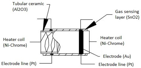
The following image depicts the components found in a metal oxide gas sensor.
 
 
sensing element in gas sensor
 
The function of each of these components is outlined as follows:
 
Gas sensing layer: This component serves as the core of the sensor, detecting fluctuations in gas concentration and inducing changes in electrical resistance. Essentially a chemiresistor, it alters its resistance based on the concentration of specific gases in the environment. Typically composed of Tin Dioxide (SnO2), which inherently possesses excess electrons (donor element), the sensing element undergoes resistance changes when toxic gases are detected. This variation in resistance influences the flow of current through the element, reflecting alterations in gas concentration.
 
Heater coil: The heater coil's role is to preheat the sensing element, enhancing its sensitivity and efficiency. Constructed from Nickel-Chromium, which boasts a high melting point, the coil maintains a constant temperature without melting.
 
Electrode line: Given that the sensing element generates minute currents upon gas detection, it's crucial to facilitate the efficient flow of these currents. Platinum wires, serving as electrode lines, aid in the seamless movement of electrons.
 
Electrode: Acting as the interface where the output of the sensing layer connects to the electrode line, the electrode allows the output current to flow to the desired terminal. Typically crafted from Gold (Au), renowned for its excellent conductivity.
 
Tubular ceramic: Positioned between the heater coil and gas sensing layer, the tubular ceramic, usually comprised of Aluminum oxide (Al2O3), boasts a high melting point. This feature aids in maintaining the preheating of the sensing layer, thereby ensuring high sensitivity and efficient output current.
 
Mesh over the sensing element: To safeguard both the sensing elements and the setup from damage, a metal mesh is deployed. Additionally, it acts as a barrier against dust particles, preventing them from infiltrating the mesh and safeguarding the gas sensing layer against corrosive particles.
 

How Does a Gas Sensor Work?

 
The efficacy of a gas sensor in detecting gases hinges on the ability of the chemiresistor to conduct current. Tin Dioxide (SnO2) is the most prevalent chemiresistor utilized, characterized as an n-type semiconductor with free electrons, also known as donors. Typically, the atmosphere contains a higher concentration of oxygen than combustible gases. Oxygen particles attract the free electrons within SnO2, causing them to migrate to the surface of the material. Consequently, in the absence of available free electrons, the output current remains at zero. The animated gif below illustrates oxygen molecules (blue) drawing in the free electrons (black) within SnO2, hindering their ability to conduct current.
 
 
gas sensor working principle
 
In environments containing toxic or combustible gases, these reducing gases (orange) interact with adsorbed oxygen particles, disrupting the chemical bond between oxygen and free electrons, thereby releasing the free electrons. As these electrons return to their original state, they regain their capacity to conduct current. This conductivity is directly proportional to the quantity of free electrons present in SnO2; thus, highly toxic gases yield a greater abundance of free electrons, resulting in heightened conductivity.
 

How to use a Gas sensor?

 
A standard gas sensor comprises six terminals, with four terminals labeled as A, A, B, and B serving as input or output, while the remaining two terminals denoted as H, H are dedicated to heating the coil. Among these four terminals, two terminals from each side are reversible, functioning interchangeably as input or output, as illustrated in the circuit diagram.
 
gas sensor pinout
 
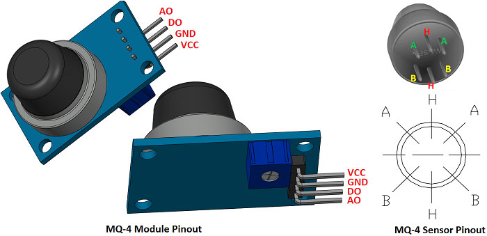
These sensors are normally available as modules (shown right), these modules consist of the gas sensor and a comparator IC. Now let’s see the pin description of the gas sensor module which we will generally use with an Arduino. The gas sensor module basically consists of 4 terminals
 
  • Vcc – Power supply
  • GND – Power supply
  • Digital output – This pin gives an output either in logical high or logical low (0 or 1) that means it displays the presence of any toxic or combustible gases near the sensor.
  • Analog output – This pin gives an output continuous in voltage which varies based on the concentration of gas that is applied to the gas sensor.
 
As previously mentioned, the output of a gas sensor typically remains minuscule (measured in millivolts), necessitating the integration of an external circuit to obtain a digital high-low output from the sensor. To achieve this objective, a comparator (LM393), adjustable potentiometer, along with various resistors and capacitors, are employed.
The LM393 comparator serves the purpose of receiving the output from the sensor, comparing it with a reference voltage, and determining whether the output is logically high or not. On the other hand, the adjustable potentiometer is utilized to establish the desired threshold value for the gas concentration, above which the digital output pin should transition to a high state.
The following diagram illustrates the fundamental circuitry of a gas sensor within a gas sensor module.
 
gas sensor module circuit diagram
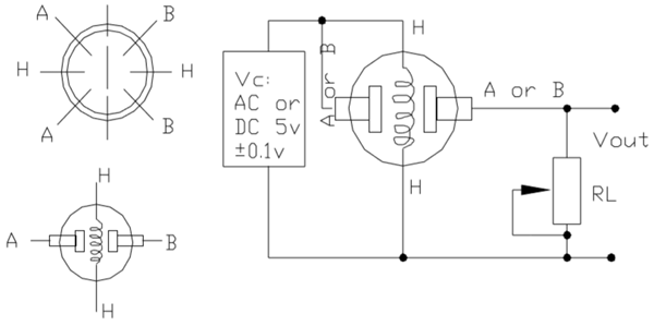
In the depicted diagram, A and B denote the input and output terminals, respectively. It's noteworthy that these terminals are reversible, implying that either of the paired terminals can function as input or output. H signifies the terminal designated for the heater coil. The variable resistor serves the purpose of adjusting the output voltage while maintaining high sensitivity.

When no voltage is applied to the heater coil, the output current remains minimal, nearly negligible or approximately zero. However, upon applying sufficient voltage to the input terminal and heater coil, the sensing layer becomes active, primed to detect any nearby combustible gases. Initially assuming the absence of toxic gases in proximity to the sensor, the resistance of the layer remains unaltered, resulting in negligible output current and voltage.

Now, envision a scenario where toxic gas is present nearby. With the heater coil preheated, detecting combustible gases becomes more facile. As the sensing layer interacts with the gases, the resistance of the material fluctuates, consequently causing variations in the current flowing through the circuit. These fluctuations can be observed at the load resistance (RL).

The load resistance (RL) value can range from 10KΩ to 47KΩ. The precise value of RL can be determined by calibrating it against known gas concentrations. Opting for a lower load resistance reduces circuit sensitivity, while a higher load resistance enhances sensitivity.
Read more…
In the dynamic realm of electronics manufacturing, soldering stands as a crucial process, binding components to circuit boards with precision and reliability. Among the myriad soldering techniques, through-hole reflow soldering and reflow soldering emerge as prominent methods, each offering distinct advantages tailored to specific applications.

Understanding the disparities between these methodologies is essential for electronics enthusiasts, hobbyists, and professionals alike. In this comprehensive guide, we delve into the nuances of through-hole reflow soldering and reflow soldering, shedding light on their unique characteristics, applications, and benefits.
 

What Is Through-Hole Reflow Soldering ?

 
Through-hole reflow soldering is a variation of traditional through-hole soldering that combines the advantages of both through-hole and surface mount soldering processes. In this method, components with through-hole leads are inserted into the PCB as usual. However, instead of relying solely on wave soldering or manual soldering techniques, the assembly undergoes a reflow soldering process, similar to that used in surface mount technology (SMT).
 
During through-hole reflow soldering, solder paste is applied to the through-hole component leads and the PCB pads. The assembly is then subjected to a reflow oven, where controlled heating melts the solder paste, forming reliable solder joints between the component leads and the PCB pads. The surface tension of the molten solder helps to precisely align and secure the components in place, ensuring optimal electrical and mechanical connections.
 
Through-hole reflow soldering offers several advantages over traditional through-hole soldering methods. It simplifies the assembly process by eliminating the need for additional wave soldering equipment, reducing the risk of thermal shock to sensitive components, and enabling the simultaneous soldering of both through-hole and surface mount components on the same PCB. Additionally, it allows for tighter component spacing and increased design flexibility, making it suitable for applications where space constraints are a concern.
 

Reflow Soldering

 
Reflow soldering is a widely used soldering technique in electronics manufacturing, particularly in surface mount technology (SMT) assembly. This process involves attaching electronic components to a printed circuit board (PCB) by melting solder paste that has been applied to the board's surface.
 
Here's how reflow soldering typically works:
 
  1. Application of Solder Paste: A stencil is used to precisely apply solder paste to the solder pads on the PCB. The solder paste is a mixture of tiny solder particles suspended in flux, which helps clean the metal surfaces and promotes solder wetting.
  2. Component Placement: Surface mount components (SMDs) are then accurately placed onto the solder paste on the PCB. This step can be performed manually or using automated pick-and-place machines, depending on the scale of production.
  3. Reflow Process: The assembled PCB undergoes a reflow process, where it is heated in a controlled manner using a reflow oven or conveyor belt system. As the temperature rises, the solder paste liquefies, creating solder joints between the component leads and the PCB pads. The reflow process typically consists of several stages, including preheating, temperature ramp-up, soaking, reflow, and cooling.
  4. Inspection and Quality Control: Once the reflow process is complete, the solder joints are inspected to ensure they meet the required quality standards. This may involve visual inspection, X-ray inspection, or automated optical inspection (AOI) systems.
 
Reflow soldering offers several advantages over traditional soldering methods, including:
 
  • High precision and repeatability: Solder paste application and component placement can be accurately controlled, resulting in consistent solder joint quality.
  • High throughput: Reflow soldering is well-suited for automated assembly processes, allowing for high-volume production with minimal manual intervention.
  • Reduced solder bridging and defects: The controlled heating during reflow helps minimize solder bridging, tombstoning, and other common soldering defects.
  • Compatibility with miniaturized components: Reflow soldering enables the assembly of small and densely packed SMDs, making it ideal for modern electronics with compact designs.
 

Key Differences

 
The main differences between through-hole reflow soldering and traditional reflow soldering are as follows:
 
1.Process Flow

Through-hole reflow soldering can simultaneously solder through-hole components and surface-mount components in a single step, simplifying the process and eliminating the need for wave soldering. Traditional reflow soldering is mainly used for surface mount devices, with the connection achieved by melting the paste solder pre-spread on the PCB pads.

2.Equipment, Material, and Labor Requirements

Through-hole reflow requires fewer equipment, materials, and manpower, helping to reduce production costs and shorten production cycles. Traditional reflow soldering demands more equipment, materials, steps, and personnel.

3.Throughput and Reliability

Through-hole reflow soldering can reduce the high defect rate caused by wave soldering and achieve a high through-hole reflow soldering rate. Traditional reflow soldering may not match through-hole reflow soldering in terms of throughput rate and reliability.

4.Applicability and Limitations

Through-hole reflow soldering is suitable for various component types, including through-hole components and surface-mount components. However, some through-hole components may not be mountable due to factors such as inherent strength, reliability, and serviceability. Traditional reflow soldering is mainly suitable for surface mount devices and may not provide sufficient mechanical strength for larger board sizes and insufficient flatness.

5.Temperature Curve and Preheating Section

Through-hole reflow soldering requires establishing a suitable temperature profile to ensure that the solder paste in the through-hole and the component pins have an appropriate reflow soldering temperature profile. Traditional reflow soldering also requires consideration of the temperature profile and preheating section to ensure soldering quality and avoid component damage from thermal shock.

In summary, through-hole reflow soldering combines the advantages of traditional reflow soldering, simplifies the process, reduces equipment and material requirements, and enhances throughput rate and reliability. However, it also has its applicability and limitations, requiring adjustments and optimizations according to specific conditions in practical applications.
 

Applications and Considerations

 
Through-hole reflow soldering finds applications in scenarios demanding robust mechanical connections, such as automotive, aerospace, and industrial electronics. Conversely, reflow soldering excels in high-volume production environments, offering unparalleled efficiency and scalability in consumer electronics, telecommunications, and IoT devices.

In conclusion, both through-hole reflow soldering and reflow soldering serve as indispensable tools in the electronics manufacturing arsenal, each with its distinct advantages and applications. By understanding the nuances of these soldering techniques, manufacturers can make informed decisions to optimize their production processes and achieve superior product quality.

Whether you're a seasoned professional or an electronics enthusiast embarking on DIY projects, mastering the intricacies of through-hole reflow soldering and reflow soldering opens doors to endless possibilities in the ever-evolving world of electronics assembly.
 

Recommend Product

 
formic acid reflow oven
Read more…
Single port trocar surgery, also known as single incision laparoscopic surgery (SILS) or single port access surgery, represents a significant advancement in minimally invasive surgical techniques. By utilizing a single entry point, surgeons can perform complex procedures with enhanced precision and reduced trauma to the patient. In this guide, we'll delve into the fundamentals of single port trocar surgery, exploring its definition, benefits, procedural aspects, and the diverse range of medical applications it serves.
 
single port trocar surgery
 

What is Single Port Trocar Surgery?

 
Single port trocar surgery involves the insertion of multiple surgical instruments through a single incision or port, typically located in the umbilicus (navel). This innovative approach eliminates the need for multiple incisions, resulting in fewer scars, reduced postoperative pain, and enhanced cosmetic outcomes. Surgeons utilize specialized instruments, including flexible laparoscopes and articulating instruments, to navigate and manipulate tissues within the body cavity.

Initially implemented in September 2018 for clinical use, single-port robotic surgery has swiftly gained traction across numerous medical facilities globally, catering to a spectrum of procedures. Surgeons across diverse specialties, encompassing urology and ear, nose, and throat disciplines, proficiently employ single-port techniques. This pioneering approach consistently yields commendable outcomes, facilitating swifter recuperation periods and heightened levels of patient contentment.
 

What’s the Difference Between Surgical Approaches?

 
Surgery offers various approaches, each tailored to individual needs, guided by your surgeon's expertise, your specific medical requirements, and overall health status.
 
Open Surgery:

During open surgery, your surgeon creates a sizable incision, necessitating more extensive tissue manipulation.
 
Minimally Invasive Surgery (MIS):

Minimally invasive surgery involves smaller incisions, leading to swifter recovery and reduced discomfort. Both laparoscopic and robotic surgeries fall under this category.
 
In traditional laparoscopic or robotic procedures, surgeons typically make three to five small incisions, known as ports, through which instruments are inserted to conduct the surgery. For instance, laparoscopic surgery might be employed for kidney removal when necessary.
 
Single-Port Robotic Surgery:

In this innovative approach, the surgeon makes just one small incision. They then utilize a single-port robot connected to the port to perform the entire procedure through this sole opening.
 

What Are the Advantages of Single Port Surgery?

 
  • Cosmetic Advantage: With only one small incision hidden within the natural contours of the umbilicus, single port trocar surgery offers superior cosmetic results compared to traditional laparoscopic or open surgeries.
  • Reduced Pain and Discomfort: By minimizing tissue trauma and nerve damage associated with multiple incisions, patients undergoing single port trocar surgery often experience reduced postoperative pain and faster recovery times.
  • Decreased Risk of Complications: The single entry point reduces the risk of infection, bleeding, and herniation commonly associated with multiple incisions, enhancing overall patient safety.
  • Enhanced Surgical Precision: Surgeons benefit from improved maneuverability and visualization provided by specialized instruments, allowing for precise tissue dissection and suturing in confined spaces.
 

What Are the Disadvantages of Single-Port Surgery?

 
Employing the single-port approach presents a greater challenge compared to traditional laparoscopy or robotic surgery due to the constrained maneuverability of instruments stemming from a singular entry point. It's imperative to ensure that your surgeon possesses regular experience in conducting these procedures and that they are performed within a hospital renowned for its high volume of such procedures annually.
 

How Do You Prepare for Single-Port Surgery?

 
Preparing for single-port surgery involves several steps to ensure optimal outcomes and patient safety. Here's a comprehensive guide:
 
  • Consultation with Your Surgeon: Schedule a consultation with your surgeon to discuss the procedure in detail. Your surgeon will evaluate your medical history, current health status, and any pre-existing conditions to determine if single-port surgery is suitable for you.
  • Preoperative Evaluation: Undergo a thorough preoperative evaluation, which may include blood tests, imaging studies (such as X-rays or MRI scans), and other diagnostic tests to assess your overall health and identify any potential risks.
  • Medication Review: Inform your surgeon about any medications you are currently taking, including prescription drugs, over-the-counter medications, vitamins, and supplements. Your surgeon may advise you to stop certain medications before the surgery to minimize the risk of complications, such as blood thinners.
  • Fasting: Follow your surgeon's instructions regarding fasting before the surgery. Typically, you will be instructed not to eat or drink anything for a certain period before the procedure to reduce the risk of aspiration during anesthesia.
  • Smoking and Alcohol: If you smoke or consume alcohol, your surgeon may recommend abstaining from these substances before the surgery, as they can interfere with the healing process and increase the risk of complications.
  • Preoperative Instructions: Follow any specific preoperative instructions provided by your surgeon, such as showering with a special antibacterial soap the night before or the morning of the surgery to reduce the risk of infection.
  • Clothing and Personal Items: Wear loose, comfortable clothing on the day of the surgery, and leave valuables and jewelry at home. You may also be asked to remove contact lenses, glasses, dentures, or other prosthetic devices before the surgery.
 

How is Single Port Trocar Surgery Performed?

 
The procedure begins with the creation of a small incision in the umbilicus, through which a specialized single port access device is inserted. This port accommodates multiple trocars or cannulas, each housing surgical instruments such as graspers, scissors, and cameras. Once inside the body cavity, the surgeon maneuvers the instruments with precision, aided by real-time imaging provided by the laparoscope. Upon completion of the surgical procedure, the instruments are removed, and the incision is typically closed with absorbable sutures or surgical glue.
 

Single-Port Surgery Is for Who?

 
Generally, individuals suitable for robotic surgery are often viable candidates for single-port surgery, with some exceptions. Moreover, individuals who may not qualify for standard robotic surgery due to factors such as multiple prior major abdominal surgeries, severe pulmonary or cardiac conditions, or morbid obesity, may still be eligible for single-port procedures. Your surgeon will evaluate your overall health status and the extent of your condition to ascertain the most suitable surgical approach.
 

Common Applications of Single Port Trocar Surgery

 
Single port trocar surgery is utilized across various medical specialties for a wide range of procedures, including but not limited to:
 
  • Cholecystectomy (removal of the gallbladder)
  • Appendectomy (removal of the appendix)
  • Hernia repair
  • Sleeve gastrectomy (weight loss surgery)
  • Colectomy (removal of part or all of the colon)
  • Hysterectomy (removal of the uterus)
 

Conclusion

 
Single port trocar surgery represents a groundbreaking advancement in minimally invasive surgical techniques, offering patients numerous benefits including improved cosmetic outcomes, reduced postoperative pain, and decreased risk of complications. By understanding the fundamentals of single port trocar surgery, patients and healthcare professionals alike can appreciate its transformative impact on modern surgical practice.
 

Disposable Single Port Trocars Manufacturer and Supplier

 
single port trocar
 
For years, Kangji Medical Instrument has been committed to providing high-quality Disposable Single Port Trocars to hospitals domestically and internationally, earning a commendable reputation. Our factory boasts hundreds of skilled professionals and cutting-edge equipment, ensuring meticulous craftsmanship. Additionally, we guarantee prompt delivery and top-notch after-sales support. We eagerly anticipate the opportunity to serve as your trusted partner in China.
Read more…

LED Drivers/Power Supplies FAQ

LED drivers, also known as LED power supplies, are responsible for delivering the necessary electricity to LED light bulbs, similar to how a fluorescent lamp relies on a magnetic ballast or a low-voltage bulb transformer. Despite their crucial role, the constant evolution of technology and the complexity of terminology can make selecting the right LED driver a daunting task, even for experienced professionals. In this article, we will explore common questions surrounding LED drivers and power supplies, clarifying their significance and functionality.
 

What Is an LED Driver and Why Do You Need One?

 
LEDs rely on three indispensable components: the chipset responsible for light emission, the driver that controls power distribution to the light source, and the heat sink crucial for cooling the unit. An LED driver serves as a vital electronic apparatus that regulates the power delivered to LED lighting systems. Unlike conventional light sources like incandescent bulbs, which can operate directly from the mains, LEDs demand precise voltage and current for optimal functionality. LED drivers play a pivotal role in guaranteeing LEDs receive the appropriate power levels, safeguarding them against voltage irregularities, and ensuring unwavering performance.
 

How Do Constant Voltage and Constant Current Drivers Differ?

 
One critical aspect to ponder is determining whether the application necessitates a constant voltage (CV) or constant current (CC) power supply. A CV driver furnishes a stable voltage output and is apt for lighting scenarios where the LED string count and current consumption remain uncertain. Here, regulating current is achieved through supplementary components positioned at the LED itself. On the other hand, CC drivers deliver a consistent current and are ideal for setups demanding direct current regulation to the LED. Such drivers function within specific voltage confines, underscoring the importance of selecting a driver with a compatible voltage rating.
 

What Is an AC LED Driver?

 
The primary role of an AC LED driver is to reduce the incoming voltage to a lower output voltage, typically around 12 or 24 Volts, to accommodate the lower voltage requirements of LEDs. When selecting an AC LED driver, it's crucial to assess your power needs since these drivers are compatible only with bulbs equipped with an internal AC to DC converter.
 

Can I Use the Driver in My Outdoor Application?

 
If your outdoor application requires a LED driver with IP67 rating, then yes, you can use the driver for your outdoor setup. This rating ensures the driver's resilience against dust and water immersion up to 1 meter for 30 minutes, making it suitable for outdoor environments where exposure to such elements is expected. Always ensure that the specifications and ratings of the LED driver align with the requirements of your specific outdoor application for optimal performance and longevity.
 

What Is Potting (Encapsulating) and Why Is It Important?

 
Potting, also known as encapsulation, refers to the process of enclosing electronic components, such as LED drivers, in a protective material, typically epoxy resin or silicone, to shield them from environmental factors like moisture, dust, vibration, and temperature fluctuations. This protective coating forms a barrier around the components, safeguarding them against potential damage and ensuring reliable long-term operation.

Potting or encapsulating LED drivers provides crucial protection against environmental hazards, mechanical stress, thermal issues, electrical faults, and corrosion. By safeguarding the internal components, potting ensures the reliable operation and extended lifespan of LED drivers, making them suitable for a wide range of applications, including outdoor and industrial environments.
 

What Are PF and PFC and Why Are They Important?

 
PF stands for Power Factor, while PFC stands for Power Factor Correction. Both are important concepts in electrical engineering, particularly in the design and operation of power supply systems, including LED drivers.
 
Power Factor (PF):

Power Factor is a measure of how efficiently electrical power is converted into useful work output. It is the ratio of real power (the power that actually performs work) to apparent power (the product of voltage and current drawn from the power source). Power Factor is expressed as a value between 0 and 1, where a PF of 1 indicates perfect efficiency, and a PF closer to 0 indicates poor efficiency.
 
Power Factor Correction (PFC):

Power Factor Correction is a technique used to improve the Power Factor of an electrical system. It involves adding circuitry to the power supply to ensure that the load presents a near-unity Power Factor to the AC power source. PFC can be achieved using passive components like capacitors (for low-power applications) or active components like PFC controllers (for high-power applications). The goal of PFC is to minimize reactive power consumption, reduce line current, and improve the overall efficiency of the power supply system.
 
Importance of PF and PFC:
 
  1. Efficiency: A high Power Factor and effective Power Factor Correction result in improved efficiency of electrical systems. This reduces energy losses, lowers operating costs, and enhances overall energy sustainability.
  2. Compliance: Many regulatory bodies and standards organizations impose Power Factor requirements on electrical equipment to ensure energy efficiency and minimize grid pollution. Compliance with these standards is often a prerequisite for product certification and market access.
  3. Stability: Power Factor Correction helps stabilize the voltage and current waveform of the electrical system, reducing voltage fluctuations and harmonics. This contributes to the stable operation of electrical equipment and prevents power quality issues.
  4. Capacity Utilization: By optimizing Power Factor, PFC enables the effective utilization of electrical infrastructure, allowing for higher equipment capacity and better resource allocation.
  5. Environmental Impact: Improving Power Factor through Power Factor Correction reduces the overall energy consumption of electrical systems, which in turn reduces greenhouse gas emissions and environmental impact associated with energy generation.
 

Does the Driver Support Dimming and Is It Flicker-Free?

 
When selecting an LED driver for your application, ensure it meets any specific requirements, such as dimming, by choosing a high-quality LED driver with seamless dimming capabilities, free from flickering. Modern wireless LED drivers are engineered to integrate with robust wireless protocols like Bluetooth LE, Zigbee, EnOcean, Thread, Z-Wave, and KNX, ensuring interference-free and nearly instantaneous feedback. Designers should familiarize themselves with the different protocols available, comparing their strengths and limitations to make informed decisions.
 

Is the Driver Compatible with Wireless Control Systems?

 
In the realm of modern lighting control systems, integration with the Internet of Things (IoT) is imperative. This entails linking devices wirelessly within a network. Should your system necessitate wireless connectivity, it's crucial to ensure that your LED drivers are equipped with wireless capabilities and can communicate effectively with other devices in your setup. The integration of connected devices facilitates the creation of energy-efficient and user-friendly systems. If your LED driver lacks compatibility with IoT protocols, numerous LED dimming module add-ons are available in the market, providing designers with additional flexibility in project design. Richard Fong, Director at GRE Alpha, highlights this modular approach as a core innovation of their system.
 

What Are the Benefits of Using High Power Efficiency Drivers?

 
High power efficiency drivers offer a range of benefits, including energy savings, extended lifespan, improved performance, compatibility with renewable energy sources, regulatory compliance, and cost savings. These drivers play a crucial role in maximizing the efficiency, reliability, and sustainability of LED lighting systems in various applications.
 

What Is the LED Driver’s Life Expectancy?

 
The life expectancy of an LED driver can vary depending on several factors, including its quality, operating conditions, and usage patterns. Generally, high-quality LED drivers designed for commercial or industrial applications can have a life expectancy of 50,000 to 100,000 hours or more.

While LED drivers typically have long life expectancies compared to traditional lighting components, it's essential to consider factors such as quality, operating conditions, usage patterns, and maintenance practices to maximize the lifespan and reliability of the LED driver in your application.

To learn more about LED drivers and power supplies, please visit gdsuncom.com or the referenced articles below.
 
Read more…

How to Unlock Induction Hob

If your household includes children or pets, there's a heightened risk of accidental contact with your induction cooktop. While having the cooktop switched off poses no threat, inadvertently leaving a burner on can lead to unfortunate hazards for your loved ones. To mitigate such risks, certain induction hobs are equipped with safety features such as a cleaning lock, child lock, and key lock, ensuring a secure and efficient cooking environment.
 

Understanding Induction Hob Locks

 
The locking feature of your induction cooktop serves not only to prevent accidental activation of the burner but also to ensure safety and prevent accidents. Before delving into the unlocking process, it's important to keep a few key points in mind:
 
Allow the burners to cool down: Always wait for a few minutes after cooking and powering off the hob before attempting to unlock it. Moving the hob around the kitchen while it's still hot can be dangerous.

Refer to the user manual: Each model of induction cooktop from HEME comes with its own user manual that provides guidance on the locking and unlocking features. Even if you've used a different model from HEME before, it's advisable to consult the manual, as each model may have slight variations in its operation.

Maintain vigilance: While the locking mechanism adds a layer of security, it's not foolproof. Pets and children can still potentially hurt themselves or cause damage if left unsupervised in the kitchen. Always keep a close eye on them to prevent accidents.
 

How to Unlock Induction Hob

 
Cleaning Lock
 
The cleaning lock feature on the induction hob prevents the operation of all keys on the control panel for a duration of 20 seconds while the hob is powered on, allowing users to swiftly clean the appliance without any power consumption.
 
To activate or deactivate the cleaning lock:
 
  • Touch and hold the cleaning lock key until a single signal sound is heard when any cooking zone is switched on.
  • A countdown timer of 20 seconds will appear on the hob's display, during which time none of the keys on the panel, except the on/off key, will be functional.
  • Deactivation of the cleaning lock occurs automatically after 20 seconds, signaled by an audio alert.
  • Alternatively, if you wish to deactivate the cleaning lock before the countdown ends, touch and hold the cleaning lock key until touch signals are heard.
 
Child Lock
 
When the cooking zones are powered off, the child lock feature can be engaged to prevent children from activating the cooking zones. Activation or deactivation of the child lock is only possible when the cooking zones are powered off and in standby mode.
 
To activate or deactivate the child lock:
 
  • Activate the child lock by simultaneously touching and holding the cleaning lock key and the stop and go key until a single signal sound is heard.
  • Once activated, the child lock function will display an 'L' on the cooking zone display, accompanied by the appearance of a decimal point above the lock key.
  • To deactivate the child lock, simultaneously touch and hold the cleaning lock key and the stop and go key until two signal sounds are heard.
  • Upon deactivation, the 'L' indicator will blink on the cooking zone display, and the decimal point above the lock key will disappear.
 
Key Lock
 
To prevent accidental changes to the hob functions while the appliance is in operation, you have the option to activate the key lock feature.
 
Activating or deactivating the key lock:
 
  • Press and hold the cleaning lock key and the stop and go key simultaneously until a single signal sound is heard. This action will activate the key lock, indicated by the appearance of a decimal point above the lock key.
  • The key lock can only be activated while the hob is in operation mode. When the key lock is active, only the on/off button will remain functional. If you turn off the hob while the keys are locked, you'll need to deactivate the key lock before you can switch the hob on again.
  • To deactivate the key lock, press and hold the cleaning lock key and the stop and go key simultaneously until two signal sounds are heard. At this point, an 'L' will blink on the cooking zone display, and the decimal point above the lock key will disappear.
 

Locked Induction Hob Causes and Solutions

 
If your induction hob's touchscreen isn't responding correctly, it could be the result of residue on the surface of the hob. Cleaning the hob with a specialized detergent and a microfiber cloth is usually enough to resolve the issue. There are also some induction hob models that feature child safety features, also referred to as button locks. Please be aware that it's possible that your hob may have been unintentionally activated by this lock if it fails to power on. To unlock it safely, refer to the instructions in the user manual.

There is also the possibility that the hob will not be able to detect the type of cookware you are using. Make sure you use iron or stainless steel cookware, or consider using an adapter between the cookware and the hob. If the controls remain unresponsive and your hob seems stuck, you can try disconnecting the power for approximately 30 minutes. Upon reconnecting the power to the hob, then try using it again. Generally, a simple reset will resolve any lingering issues that you may encounter.

If you're still having trouble unlocking the hob no matter how hard you try, you can contact the manufacturer's customer service department for assistance and guidance.
 

Conclusion

 
Unlocking your induction hob is a simple yet essential skill for any home chef. By following the steps outlined in this guide and staying patient, you'll be able to unlock your hob with ease and get back to cooking your favorite meals in no time. Don't let a locked hob stand in the way of your culinary adventures – unleash your cooking potential today!
 

Related Products

 
HEME offers a range of built-in 45 cm induction hobs, each equipped with three touch induction zones made of glass ceramic.
 
NnSD4xFMWn.webp?profile=RESIZE_400x85CDiX3EeR.webp?profile=RESIZE_400xmXcGQhSK2S.webp?profile=RESIZE_400x
Read more…

Ultimate Guide to Laser Cut Panels

Pictures and posters are a popular and conventional means of embellishing any space, be it personal or professional. However, why settle for blending in when you can truly make a statement? Infuse vibrancy into your walls with distinctive designs that inject personality into your living or working environment. Discover the growing global appeal of laser cutting and how it has the transformative power to elevate any envisioned design into a captivating work of art.
 
laser cut decorative metal panel
 

What Are Laser Cut Panels?

 
Laser-cut screens feature intricate patterns and designs etched into a chosen material. Our screens are crafted from a variety of materials including aluminum, stainless steel, mild steel, and corten steel. They serve versatile purposes and can be utilized in diverse settings such as luxury hotels, restaurants, offices, apartments, and homes. Tailored to suit any space, these screens seamlessly blend into their surroundings. Opting for laser-cut panels over conventional framed or unframed photographs offers numerous advantages. Virtually any design concept can be translated into a stunning masterpiece. Combining the robustness of steel with an elegant aesthetic, these panels are both lightweight and durable. Using metal as the medium ensures resilience against damage, even with frequent handling, promising longevity far beyond that of traditional photographs or pictures.
 

What Metals Can Be Laser-Cut?

 
A significant benefit of laser cutting lies in its versatility, capable of cutting through a wide array of materials ranging from thin metals to thicker ones, including wood and select types of plastic.

Laser cutting encounters minimal obstacles with most grades of:
 
  • Mild steel / Low Carbon steel
  • Cold rolled steel
  • Stainless Steel
  • Aluminum
  • Titanium
  • Brass
  • Copper
 
With the introduction of CO2 laser cutting technology, the precision and swiftness typically associated with thinner materials can now be extended to thicker materials as well.
 

What Is the Process of Laser Cutting Sheet Metal?

 
Laser cutting of metal involves the utilization of laser beams to liquefy metals and alloys, resulting in precise, clean cuts. This process comprises two synchronized operations.

Initially, the material absorbs the concentrated laser beam, which provides the energy necessary for cutting. Subsequently, the cutting nozzle, aligned with the lasers, supplies the requisite process gas. This gas shields the processing head from vapors and splatters while aiding in the removal of excess material from the kerf.

Primarily, there are three techniques for laser cutting sheet metal:

1.Laser Beam Fusion Cutting

In laser beam fusion cutting, an inert gas, typically nitrogen, is used. This low-reactivity process gas continually vaporizes the material's cutting gap. By preventing oxidation at the cutting edge without impeding the process, inert gas facilitates the removal of molten material. This method is suitable for cutting flat, thin sheets of aluminum alloys and stainless steel, resulting in high aesthetic appeal and minimal finishing operations.

2.Laser Beam Sublimation Cutting

Laser beam sublimation cutting entails the immediate evaporation of material, transitioning directly from solid to gas (sublimation). Similar to fusion cutting, inert gases are employed to expel the material's vapor from the kerf, ensuring no oxidation occurs at the cutting edge. This method finds application in cutting organic materials like wood, leather, and textiles.

3.Laser Beam Flame Cutting

Laser beam flame cutting utilizes a combustible gas—oxygen—to expel molten material. The laser heats the workpiece, inducing spontaneous combustion post-melting. Oxygen gas enhances the cutting process through oxidation—an exothermic reaction. Ideal for cutting mild steel and fusible materials such as ceramics, this method may result in burns on the cutting surface due to the oxidizing nature of the gas. Proper adjustment of process parameters can mitigate the formation of burrs.
 

7 Benefits Of Sheet Metal Laser Cutting

 
Let's explore the advantages of using laser cutting for sheet metal in the manufacturing sector:
 
1.Precision and Accuracy
 
Laser cutting excels in precision, making it ideal for intricate cuts with tight tolerances. Machines are capable of achieving extreme precision, often up to 0.0005 inches. This accuracy is crucial for manufacturing processes requiring detailed specifications. Additionally, laser cutting produces minimal burrs, leaving behind clean, smooth edges.
 
2.Automated Process

Utilizing Computer Numerical Control (CNC) systems, laser cutting operates autonomously once programmed. This automation reduces the need for human intervention and labor while enhancing cutting efficiency.
 
3.Damage Prevention
 
Contrary to misconceptions, laser cutting minimally affects materials, preventing warping or distortion. The heat from lasers selectively targets specific areas, leaving surrounding material unaffected. Consequently, there's minimal risk of damage to the workpiece.
 
4.Compatibility with Various Materials
 
Laser cutting is versatile, capable of handling a wide range of materials including copper, aluminum, stainless steel, and titanium. Its ability to cut through various materials efficiently makes it a preferred choice for diverse manufacturing applications.
 
5.Cost-Effectiveness
 
Although laser cutting machines may have initial costs, they offer long-term cost savings. A single laser cutting machine can handle multiple cutting operations without the need for modifications. Moreover, the minimal maintenance requirements and reduced operational costs make it a cost-effective solution compared to traditional manufacturing tools.
 
6.Versatility
 
Laser cutting offers versatility, accommodating a wide range of cutting functions from simple to complex tasks. Its ability to handle intricate designs and tight tolerances makes it suitable for various industries and applications.
 
7.Low Energy Consumption
 
Despite requiring power for operation, laser cutters are energy-efficient compared to alternative cutting methods. The machines have fewer moving parts, resulting in lower energy requirements. Additionally, their high-speed cutting capability reduces energy consumption and saves time.
 
laser cut screens for gardens and balconies
 

What Is the Best Place to Use Laser Cut Panels?

 
Are you an interior decorator seeking to offer your clients something distinctive, elegant, and of superior quality, yet affordable? Whether your clientele comprises families, small businesses, or larger establishments like hotels, restaurants, or companies, our laser-cut panels are tailored to suit each of their needs. By blending their preferred colors, patterns, and materials, and incorporating backlighting, you can transform their space into an inviting area that they, along with their friends or customers, will relish spending time in.

1.Residential and Commercial Spaces

Elevate the decor of your home or office beyond traditional wall hangings such as photographs or paintings. Huijin Metal provides an avenue for creative expression with a myriad of panel design options. Imagine bringing the essence of a forest or the majesty of a sea wave into your room. By mixing and matching colors, patterns, and materials, you can curate your own masterpiece. Backlighting adds another dimension, allowing you to set the ambiance according to your preferences, whether it's a romantic setting or a lively atmosphere for celebrations. Additionally, installing backlighting can help conserve energy and save on utility costs, while transforming any space into a captivating environment.

2.Hospitality and Retail Environments

In customer-centric settings like hotels, restaurants, and shops, laser-cut panels serve a dual purpose beyond mere decoration. They can convey a message or narrate the story of your business through customized displays of logos, slogans, or mission statements. These panels not only enhance aesthetics but also serve as durable promotional tools that can withstand the rigors of daily use. Our signage products, including those with background lighting, are particularly popular for interior and exterior applications in various commercial settings. They can be customized to meet your specific branding and promotional needs, ensuring a lasting impression on your clientele.

3.Outdoor Spaces

Our panels and walls are not confined to indoor use but are also suitable for outdoor applications in gardens or on balconies. Crafted from weather-resistant materials, they are designed to withstand outdoor elements, ensuring longevity and durability. Before selecting a decorative wall for outdoor use, consult with us to receive professional advice on the best materials for your specific requirements and how to properly maintain them for optimal longevity.

We can help you choose the perfect solution for your space by contacting inquiry@huijinwiremesh.com.
 
Read more…

A Guide to Selecting RF Switches

RF switches serve the purpose of directing radio frequency (RF) signals among different inputs and outputs. They find extensive application in RF and microwave test systems, facilitating the routing of signals between instruments and devices under test (DUT). Utilizing RF switches enables the execution of multiple tests without necessitating alterations to the setup, thereby enhancing efficiency by minimizing the frequency of connections and disconnections.

To exemplify the simplification of intricate signal routing through the use of RF switches, let's consider matrix switching. In the illustration below, six single-pole, triple-throw (1P3T) switches are employed to route three RF signals. The colored lines indicate the trajectory of each input signal, with the flexibility to reroute signals via any of the black lines by adjusting the switches. This design exclusively relies on switches, eliminating the need for power dividers or attenuators, thereby ensuring low insertion loss and exceptionally high signal isolation.
 
matrix switch
 

Types of RF Switches

 
Based on the switching action of RF switches, there are two different types of switches which can be classified as follows:
 
Electromechanical Switches

Electromechanical switches incorporate metal contacts that can either be in a physically open state, halting the flow of current or signal, or closed, completing the circuit and enabling current to pass through. These switches are characterized by the number of circuits they can connect, known as "poles," and the distinct positions they can assume, referred to as "throws." For instance, a single pole, single throw (SPST) switch functions as a basic on-off device, either establishing or breaking one circuit. Conversely, a double pole, single throw (DPST) switch operates two connected circuits simultaneously. In contrast, a double throw (DT) switch can alternate between two separate circuit paths. Various schematics of electromechanical switches are depicted below.
 
Electromechanical switches offer versatility across broad frequency ranges and boast features such as low signal loss and minimal cross talk between channels. However, they present certain drawbacks due to their reliance on physical movement for operation:
 
  • Unreliable or slow switching caused by contact bounce.
  • Arcing between contacts.
  • Susceptibility to electromagnetic interference.
 
Solid State Switches
 
Solid-state switches are semiconductor devices that operate without mechanical switching mechanisms, enabling them to switch signals rapidly. Due to their robust resistance to shock, vibration, and mechanical wear, they are perceived as more reliable and durable compared to electromechanical switches. However, solid-state switches typically exhibit higher insertion loss than their electromechanical counterparts.

Solid-state switches leverage three primary semiconductor technologies to facilitate effective signal switching:

PIN Diode Switches: PIN diodes function as variable resistors at RF and microwave frequencies. Controlled by current, they adjust their resistance to either a lower state (ON or "make") or a higher state (OFF or "break"). Despite their capability to handle large RF signals with minimal control current, PIN diode switches are generally limited to lower frequency operations (< 1 MHz). Within this range, they offer superior isolation characteristics, especially at higher frequencies. The image below depicts three different SPDT PIN diode switch configurations: series PIN (top), shunt PIN (middle), and series-shunt PIN (bottom).
 
pin diode circuits
 
Field Effect Transistor (FET) Switches: FET switches utilize semiconductor devices to regulate the conductivity of a channel within the semiconductor material. They consume less current and exhibit higher insertion loss than PIN diode switches. FET switches feature excellent isolation at lower frequency ranges but tend to switch more slowly compared to PIN diode switches. Isolation characteristics may degrade at higher frequencies due to drain-to-source capacitance.
 
an spdt fet switch
 
Hybrid Switches: Hybrid switches integrate both PIN diodes and FETs, combining the advantages of both switch types. They consume moderate power, offer excellent isolation at high frequencies, and demonstrate average switching speeds.
 
Manual Switches
 
Apart from solid-state and electromechanical variants, certain RF switches are manually operated. These devices necessitate human intervention to manipulate a knob or slide, facilitating switching. Manual switches commonly accommodate high-power signals and find frequent application in toggling between multiple antennas and RF transmitters/receivers.
 

Factors to Consider When Selecting RF Switches

 
When selecting RF switches for specific applications, several factors must be carefully considered to ensure optimal performance and compatibility. Here are the key factors to take into account:
 
  1. Frequency Range: Determine the operating frequency range required for your application. Ensure that the RF switch's frequency capabilities align with the frequency range of the signals being handled.
  2. Insertion Loss: Evaluate the insertion loss of the RF switch, which refers to the amount of signal power lost when passing through the switch. Lower insertion loss is desirable for maintaining signal integrity.
  3. Isolation: Consider the isolation performance of the RF switch, which refers to its ability to prevent unwanted signals from leaking between different ports. Higher isolation ensures minimal crosstalk and interference.
  4. Switching Speed: Assess the switching speed of the RF switch, which determines how quickly it can transition between different signal paths. Faster switching speeds are advantageous for applications requiring rapid signal routing.
  5. Power Handling: Determine the power handling capability of the RF switch, which specifies the maximum power levels it can safely handle without degradation or damage.
  6. Control Interface: Consider the control interface of the RF switch, such as whether it requires DC voltage, TTL signals, or other control mechanisms for operation. Ensure compatibility with your system's control scheme.
  7. Reliability and Durability: Evaluate the reliability and durability of the RF switch, particularly in terms of mechanical robustness, temperature stability, and longevity. Choose switches that can withstand the environmental conditions and operational requirements of your application.
  8. Size and Form Factor: Consider the physical size and form factor of the RF switch, especially if space is limited or if integration into a compact system is necessary.
  9. Cost: Assess the cost-effectiveness of the RF switch, taking into account factors such as initial purchase price, long-term maintenance costs, and overall value for your application.
  10. Application Specific Requirements: Take into consideration any specific requirements or constraints of your application, such as environmental conditions, regulatory compliance, and compatibility with existing equipment or systems.
 
By carefully evaluating these factors and selecting RF switches that best meet your application's needs, you can ensure reliable performance and optimal functionality in your RF system.
Read more…